|


|


"Television is the first truly democratic culture - the first culture available to everybody and entirely governed by what the people want. The most terrifying thing is what the people do want."
-- Clive Barnes, New York Times, 1969
This chapter is a little different from the others. As this textbook was designed to be a reference to a course at Ryerson University in Toronto, Canada, the first seventeen chapters each corresponded to a section within that course.
The Appendix section, where you are now, is an "in depth" area where some ideas and concepts can be more thoroughly discussed - some that are either too technical for the original course (designed for the Radio and Television Arts program, not an engineering school), or that may be historical in nature.
You may have been led to this chapter by a link from another chapter, recommending that you check the Appendix section for more information. In those cases, at the end of those Appendix sections, there will be a link to get you back to where you were reading in the other chapter!
Choose from the links below to jump to the various sections within this chapter. Enjoy!
|
Audio
Phonograph Records
Cassettes
Tape Heads
Tracks
Compact Disc
Digital Audio Tape
Video
The Colour Encoding Process
Waveform Monitor Quick Reference Card
Vectorscope Quick Reference Card
Waveform and Vectorscope Printable Reference Card
Cameras
How To Do A Camera Lineup
Colour Balance
Why Bother Explaining This?
Video Recording and Reproducing
Colour Under System
Time Base Correction For Air
Digital Time Base Correction
|
Transmission
The History of Satellites
Canada's Role In All Of This
Audio Transmission Techniques
Other Satellites
World Television Standards
NTSC
PAL
SECAM
Scanning Rates
Apocryphal Stories
Whatever Happened to Channel 1?
Creation of UHF
The Invention of PAL and SECAM
The First Public Showing of Videotape
World TV Standards
Did You Know?
Looping
Battery Belt Shooting and Charging
Speakers and Magnets
Videotape Storage and Handling
How Head Cleaning Tapes Work
Videotape Acclimatization
Cleaning Equipment of Dust
Testing Microphones
Quartz Bulbs
"...Because It Doesn't Know The Words" |
Audio
Phonograph Records
To play a stereo record, the disk is placed on a turntable that rotates at a constant speed. A tone arm carrying a stereo cartridge is mounted next to the turntable. The arm usually pivots to rest its stylus lightly on the record groove and to track the two sound channels inscribed in the groove walls. (Less common is linear tracking, in which the tone arm is mounted on a track. Driven by a separate motor, the entire arm moves in the track as the stylus follows the grooves, and - unlike the pivoted tone arm - maintains the same optimal position in relation to the grooves over the entire surface of the record.) The stylus vibrates in response to the variations in the grooves, and the vibration is converted into an electrical signal, which, when strengthened by an amplifier, drives the loudspeakers. There the signal is converted back into acoustic vibrations.
For the most part, LP stereo records have been replaced by other formats, notably compact tape cassettes and compact discs.
Compact Cassettes
In a standard tape recorder the tape is spooled off a supply reel, threaded past the recording and playback heads, and rewound on a takeup reel. During the 1950s and 1960s many efforts were made to enclose reels and tape in a self threading package to end the inconvenience of tape handling. By far the most successful design was the compact cassette, a small plastic box containing reels and tape, introduced by Philips in 1964. Since the tape in the cassette was only 0.15 inch (0.38 cm) wide and moved at only 1 7/8 inches per second, a pocket size cassette could accommodate an hour long recording. By 1970, with refinements in electronics, in tapes and recording heads, the cassette delivered high fidelity stereo sound.
Cassette tapes have made music portable. In-dash stereo cassette players were developed for automobiles during the 1970s, followed by a broad range of battery powered "go anywhere" tape players in the 1980s - from tiny personal headphone units to loud "boom box" portables. By 1983 the compact cassette was the most popular medium for recorded music, and it was widely used for other applications as well, including telephone answering machines and as a program storage medium for low cost home computers.
Tape Heads
You should be aware of what adjustments are made and problems that will result when heads are out of alignment. Some of these terms will be discussed when we delve into videotape recording in later sections.
|
Zenith: the "tilt forwards or backwards" vertical angle of the heads, to maintain uniform tape tension across the entire width of the tape, top to bottom. If set incorrectly, the tape will skew - ride up or down on the head.
Height: If the heads are not at the right height with regard to the tape width, the result can be signals that are only partially recorded or played back, crosstalk between tracks, noise, or poor erasure.
Tangency: the angle of the head to tape contact at the head gaps (the head gap is the space between the poles of a magnetic tape head). If this is set incorrectly, high-frequency response will suffer, and there may be signal dropout.
Wrap: similar to tangency, but is the angle at which the tape curves around the head. This must be correct otherwise symptoms similar to tangency may result.
Azimuth: The head must be exactly perpendicular to the tape, otherwise recordings (and playbacks) will have reduced frequency response.
|
Tape head problems
|
Tape Tracks
Various audio tape track formats
Several track formats and widths exist in audio tape recording. Note that a channel is not necessarily a track. A channel is a conduit through which signals flow. A track is the physical path on the tape itself.
Compact Disc
The compact disc (CD) digital record is based on technology created for the optical videodisc. The "Laservision" system, which uses a low-power laser to read a video signal encoded as a series of microscopic pits in a reflective disc, was developed by Philips in Holland during the mid-1970s. It was later adapted for digital audio as the compact disc recording.
While American companies created the materials and devices that made digital records possible (lasers, plastics, computer circuits, pulse-code-modulation encoding, and integrated circuit chips), the CD system was developed by Philips in Europe, and Sony in Japan. An industry committee adopted the CD format as an international standard, and CDs first appeared on the market in 1983. The CD is 12 centimetres in diameter and contains up to 74 minutes of music in two-channel stereo. The digital code is engraved on the disc in the form of microscopic pits along a track that begins near the centre of the disc and spirals outward toward the edge. The pits are about 0.5 micrometers wide, with a uniform 1.6 micrometer spacing (1 micrometer is 1/1000 of a millimetre). As this spacing corresponds to the wavelength of visible light, CDs display a distinctive, colourful rainbow on their surface.
The success of the CD has spawned several alternative formats: the mini-CD, a 3 inch disc limited to 20 minutes of music; CD-V, or CD-Video, containing 20 minutes of music plus 5 minutes of video; CD-ROM, CD-read only memory, containing 650 megabytes or more of computer-coded data or programs; and CD-I, CD-Interactive, containing a mix of audio, video, and computer programming for entertainment or educational use.
For playback, a laser is focused through the transparent rear surface of the disc onto the aluminized pits, and an optical sensor detects the alternately strong and weak reflection. Small scratches and dust particles on the plastic surface have little effect, since they are out of focus. The disc plays from the centre out, rotating about 500 revolutions per minute (rpm) initially, and gradually slowing to about 200 rpm as the spiral track approaches the rim, so the pits pass under the laser beam at a constant linear speed of 1.25 meters (4 feet) per second. After de-interleaving and error correction, the digital code is fed to digital-to-analog converters and output filters that recreate the original audio waveform in each channel.
Digital Audio Tape
Digital audio tape (DAT) machines made for studio and at-home recording employ the same 16-bit PCM code as the CD, with similarly elaborate interleaving and error correction. The digital code is recorded on tape in helical scan format, using a similar but smaller version of the mechanism in an 8mm VCR or camcorder.
A helical scan rotary head is used, rotating at 2,000 rpm. Although the linear tape speed is only 1/6 that of a regular cassette (8.15 mm/sec), this rotating head makes the effective head-to-tape speed 3.133 metres per second. The tape wraps around the scanner by only 90 degrees, and the signal is recorded by two audio heads, laying down tracks that are inclined +20 and -20 degrees in azimuth. The recording medium is a metal powder tape.
[This link will return you to the Popular Audio Recording Formats section in the Audio Chapter]
Video
The Colour Encoding Process
The NTSC colour encoder
For those timid of algebra and words like "equation" and "vector," I'll try to be as clear as I can. Here we go...
Step 1
Our original red, green, and blue signals are "boiled down" into another set of signals. First, a "Y" or luminance signal is created. This looks like this as an equation: Luminance= 30% Red + 59% Green + 11% Blue.
Step 2
Two other signals are rather unique. They are called "R-Y" and "B-Y," and are made up by mixing the red channel and an electronically inverted version of the luminance, and the blue channel and an electronically inverted version of the luminance, respectively.
Believe it or not, with Y, R-Y, and B-Y, we can re-assemble our R, G, and B values anytime we like. This is the basis of component video. That's all very well, but we've still got a problem: these three signals, while rather intriguing, still have to be squeezed down one transmission line.
Well, we can't just mix them together in equal (or even unequal) proportions. The result will be a jumble of three video signals, that can't be taken apart once it's put together, sort of like a sound mix - you can't separate the sound of individual instruments once the mix is done. Time to get clever.
Step 3
3 (a). What we're going to do is somehow encode our R-Y and B-Y signals into our previously mentioned high-frequency sine wave type of signal, which we then can mix with the luminance signal for transmission. We'll choose a frequency high enough that you can't normally see it on a black and white monitor (except, maybe, for some little dots from time to time). And, since this high frequency wave is going to carry our colour information for us, we'll call it the subcarrier.
By convention, our maximum video bandwidth is 4,200,000 cycles per second. That's the maximum number of cycles of voltage swing we can transmit on a television channel every second. We could make this subcarrier that high a frequency, making the finest, most inconspicuous dot pattern possible in black and white. But, there is a problem with doing that.
3 (b). We're going to "modulate" this subcarrier. What exactly does that mean? A modulator is a kind of "valve" which takes in two signals. One of them is our high-frequency carrier wave. The other is our lower frequency signal that can make the modulator do one of a few things - either change the amplitude (level) of the carrier, or change its phase, or even slightly alter its frequency.
When you amplitude modulate a sine wave carrier, you create artifacts called sidebands. In essence, they're a couple of signals that appear at frequencies greater than, and less than, the sine wave carrier frequency. They extend, in fact, by the amount that is the maximum frequency encountered by our R-Y and B-Y signals. If, therefore, we were to shove our subcarrier right up to the edge of our 4.2 MHz (megahertz) bandwidth, one of our sidebands that we'd create would go beyond this bandwidth. This would cause all kinds of interference with the sound information that's normally placed at the top end of every television channel. So, let's drop our subcarrier rate back a little. But by how much, since we want to reduce the dot pattern on black and white monitors?
Well, we get lucky again. As it turns out, the human eye cannot discern colour in extremely small areas of a scene - we see fine detail only as shades of grey. Armed with this information, we don't need to send our colour information with the bandwidth of a full video channel. In fact, we can limit these signals to about 500,000 cycles per second.
3 (c). Back to the subcarrier frequency. If we lowered it to, say, 3,600,000 or so, that would leave us with a little headroom even if we created a sideband 500,000 cycles above that (3,600,000 + 500,000 = 4,100,000 cycles per second). In fact, the frequency we've chosen to do this vital work is exactly 3.579545 MHz.
3 (d). Before we get too smug about having chosen the perfect frequency, consider that we still haven't modulated anything onto it yet. We can't just mix the R-Y and B-Y signals together and modulate - they'll be a jumbled mess, like we mentioned earlier. We have to get clever once again. We're going to use two modulators, and special ones at that.
Remember how we defined one kind of modulation as taking a carrier signal and changing its level relative to the input signal? There's a special type of modulator called a "balanced modulator" which gives no carrier output when there is no modulating signal fed to it. When a signal is fed to the balanced modulator, its output is proportional to the level of the signal being fed, with one special attribute: if the signal being fed to it is "positive," the output of the modulator's carrier is at 0 degrees phase, but if the signal being fed to it is "negative," the output of the carrier is at 180 degrees phase.
How balanced modulators work
A simple example of this: if you feed a low frequency sine wave to a balanced modulator, for one whole cycle of the wave, the carrier output will appear like this:
|
Input Wave
|
Level of Output From Balanced Modulator
|
Phase of Output From Balanced Modulator
|
|
Zero amplitude
|
No output
|
No output
|
|
Increasing to maximum positive wave
|
Grows from zero to full level
|
0 degrees
|
|
Maximum positive amplitude
|
Maximum
|
0 degrees
|
|
Decreasing back to zero
|
Level diminishes
|
still 0 degrees
|
|
Zero amplitude
|
No output
|
No output
|
|
Increasing negative amplitude
|
Grows from zero to full level
|
180 degrees
|
|
Maximum negative amplitude
|
Maximum
|
180 degrees
|
|
Decreasing back to zero
|
Level diminishes
|
still 180 degrees
|
|
Zero amplitude
|
No output
|
No output
|
Step 4
4. So, now we have two of these special balanced modulators available to us, and we're going to feed the R-Y signal into one of them and the B-Y signal into the other. The outputs of these two modulators will be mixed together.
To prevent these mixed modulators from interfering with each other (again, like an audio mix), we still have one more trick to perform. We're going to put one of the modulators' outputs out by 90 degrees with respect to the other. So, our B-Y modulator will vary in amplitude, and, when notified to do so by our B-Y input signal, also vary in phase flipping between 0 and 180 degrees. Our R-Y modulator, on the other hand, also will vary in amplitude but will vary in phase between 90 and 270 degrees.
When we finally mix these two modulators together to create the colour subcarrier, something quite interesting happens. Depending on what colour is present in the video signal, you will get a particular phase of the subcarrier at that point that is a sum of the two balanced modulators' mix, most of the time somewhere between the hard and fast phases of 0, 180, 90, and 270 degrees. Any possible colour can be shown to have a particular phase of subcarrier. The intensity of the colour is proportional to the amplitude of the subcarrier. These are, of course, usually displayed to us as vectors around a circle - on our vectorscopes.
Step 5
5. Finally, we can mix this "variously phased" subcarrier signal onto our luminance signal, and we will have created a composite colour television signal.
Take a deep breath here...
Not Quite Done
Now, just when you feel you've understood how colour television encoding works, there are a few more wrenches to throw in.
The first wrench is that, if we were to allow the full amplitudes of the R-Y and B-Y signals to go unchecked, we'd find that some picture material having high luminance values and high colour saturation would force our brand-new composite colour signal way over 100 units of video. For that reason, the R-Y signal is usually limited to 87.7% of the full range, and the B-Y signal is limited to 49.3% of the maximum.
The next consideration is that we have not provided any way of telling our colour monitor exactly what degree of subcarrier is which colour - it will have no reference from which to work when decoding all this information. We should send a little "blip" of "known" degrees subcarrier just after the horizontal synchronizing pulse, to tell the monitor "this is your reference for the next line of video." This is called the colour burst, and is several cycles of 3.58 MHZ subcarrier at 180 degrees phase.
Another wrinkle: we've modulated our colours at this point so purplish-blue, greenish-yellow, purplish-red, and greenish-sky blue are the colours falling at 0, 180, 90 and 270 degrees, respectively. This is fine. But, wouldn't you know it, greenish-yellow and purplish-red are the colours that humans are least sensitive to, for discerning detail. Seems like a waste to put our maximum amplitudes of colour definition into these particular hues. Back to the drawing board...
Our eyes are particularly acute at seeing detail in orange hues (maybe that's why we like sunrises and sunsets so much). If we were to run our balanced modulator at the phase angles that represented these particular colours, we would be giving ourselves the benefit of modulating on an axis that is most sensitive to our eyes.
|
There's another advantage, too - the orange hues are where most flesh tones are located. In a monitor, a small fault in either of its demodulators will tend to reproduce quite inaccurate hues of a colour whose phase is determined by both modulators. A fault in a demodulator, however, will only change the saturation, not the hue, of a colour that is based on that one modulator's particular phase axis. So, for more accurate flesh tones (which seem to bother us more than incorrect colours of background scenery), we should place one modulator's axis on this particular colour's phase.
And that, in fact, is what we finally did. Our two balanced modulators' actual phase changes flip between 123-303 degrees (orange and blue), and 33-213 degrees (magenta and yellow-green), respectively. Notice that they're still out by 90 degrees to each other. We had to call these two new modulating phases (and their modulators) something. The one using orange's phase as its reference was called "I" for "In phase with orange," while the other was called "Q" for "in Quadrature phase with the first one."
|
R-Y and B-Y axes, versus I and Q axes
|
One last hitch and then we're done - honest.
Up until now, we've been saying how television scans 525 lines in 1/30 of a second. Well, that's not exactly true. You see, it was true in the days of black and white television. But, to keep the visibility of the colour subcarrier in the monitor to a minimum (the "little dots" we referred to earlier), a couple of the specifications got changed.
In black and white television, 525 lines scanned in 1/30 of a second gave us a line scan rate of 15,750 Hz (525 x 30). That was changed to be precisely related to the subcarrier frequency - 2/455 of it, in fact - which made it 15,734 Hz (2/455 x 3,579,545 Hz).
Having changed the line scan rate, the frame rate also had to change, from 30 frames a second, to 29.97 frames a second (15,734 / 525).
There now...wasn't that easy?
[This link will return you to the Colour Encoding in Detail section in the Analog Video Chapter]
Waveform Monitor Quick Reference Card
|
Waveform Monitor Quick Reference Card
|
|
Input Controls
|
|
Filtering
|
selects FLAT, LPASS, or CHROMA
|
|
Reference
|
EXT or INT sync
|
|
Input
|
which video source to monitor
|
|
Vertical
|
|
Gain
|
expands waveform vertically
|
|
DC Restoration
|
references display to sync pulses; prevents floating display
|
|
Position
|
vertically aligns waveform
|
|
Horizontal
|
|
Sweep
|
displays 1 line, 2 lines, or 2 fields
|
|
Magnification
|
expands display horizontally (1 Fs/div, or shows vertical interval)
|
|
Field
|
selects F1 or F2 for display
|
|
Position
|
horizontally moves waveform display
|
|
Display
|
|
Focus
|
focuses CRT image
|
|
Scale Illumination
|
brightness of graticule
|
|
Intensity
|
brightness of CRT image
|
|
Line Selector
|
chooses individual line to display
|
Vectorscope Quick Reference Card
|
Vectorscope Quick Reference Card
|
|
Input Controls
|
|
Reference
|
EXT or INT sync
|
|
A/B
|
which video source to monitor
|
|
Gain
|
|
Variable
|
varies length of vectors for detailed viewing
|
|
Phase
|
rotates vectors; usually set so that colour burst is at 180 degrees
|
|
Display
|
|
Focus
|
focuses CRT image
|
|
Scale Illumination
|
brightness of graticule
|
|
Intensity
|
brightness of CRT image
|
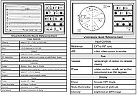 Printable Waveform and Vectorscope Quick Reference Card
Click on the picture to the left for a large scale quick reference card, suitable for printing from any graphics program.
Cameras
How To Do A Camera Lineup
All cameras should be set up first thing each day and before each new location over the course of the day. With the modern technology available to us, this is commonly reduced to:
 |
Put camera on lit chip chart; hit "auto white" and "auto black" switches.
|
|
Shoot pictures. Have a nice day.
|
But could you do a camera balance manually?
Colour Balance
|
Set up the camera on a chip chart, so the arrows on the edge of the chart fit to the edge of the raster of the camera's scan. Be certain that the chart is lit evenly top to bottom and left to right, using a light meter. Turn all paint pots to 12 o'clock; set blacks to 7.5 units and iris so the white chip just reaches 100 IRE.
|
|
Select ENC (encoded) on the TEST OUTPUT selector. Select FLAT response on the waveform. Starting with the red and blue BLACK PAINT pots, null out any subcarrier (colour) in the blacks. Move to the red and blue GAIN (or WHITE PAINT) pots and do the same. Go back to the BLACK PAINT pots and null again. Repeat until the chips have as little overall subcarrier as possible.
|
|
When finished, pull out on the camera to a wide shot and fine- tune the colour balance from the paint pots, so the cameras look as close to a match as possible.
|
|
"Chip" chart (logarithmic reflectance chart)
|
Why Bother Explaining This?
Some consider the above explanation to be redundant in the light of today's automatic lineup systems.
For several reasons, it is a good idea to understand just what happens inside the camera when you press, say, AUTO WHITE.
Maybe some day your AUTO WHITE might not work any more. In that case, a familiarity with "manual override" procedures will allow you to get on the air as soon as possible, with the least amount of disruption.
Not all facilities that you'll be working in over the years may be as fortunate to have fully automatic lineup. In that case, a qualified CCU, camera and/or lighting operator will be required and expected to know all about camera principles and manual camera lineup procedures. It does no harm to be well versed in these methods.
Besides, sometimes, even after doing automatic lineup, you will find that the shot just doesn't look "right." The painting is not nearly what you expected, and so you will have to understand how to manually paint a camera for each shot. This is easily done by looking at the shot on a waveform monitor in the FLAT response position, slightly uncrushing the black levels, and nulling out the blacks and whites as necessary.
Video Recording and Reproducing
Colour Under System
How a VHS machine can play back pictures to a television monitor (The "colour under" system)
To describe this, we first have to digress briefly into the theory of heterodyning. This is nothing more than the generation of the sum or difference signals when two sources are introduced to our old acquaintance, the balanced modulator.
As an example, if frequencies of 200 and 300 Hz are input to a balanced modulator, the outputs of the modulator will be 100 and 500 Hz (the sum and difference of the two input signals). This is called "heterodyning" the 200 Hz signal with 300 Hz.
The aim of the heterodyne "colour under" technique is to remove the time base jitter from the chrominance signal only so the video can be displayed on a regular picture monitor with enough stability. Removal of the time base error from the luminance information isn't a requirement, since a television set or monitor has adequate horizontal lock stability to compensate for it.
To achieve this, the colour video signal is first separated in its luminance and chrominance components. The chrominance part is then heterodyned with a stable frequency oscillator; the output of the modulator is our chrominance information centred around 688 KHz.
The luminance signal is recorded onto the tape using the standard FM technique similar to that described in quad machines. The "down converted" chrominance is recorded directly on the tape with the luminance FM carrier acting as a bias (as in audio tape recording).
You now have the luminance information recorded as FM around the 4.2 MHZ range, and the chrominance recorded around the 688 KHz range - thus the term "colour under." Let's now play back this signal.
The playback signal from the tape is separated into the FM subcarrier and the relatively low frequency chrominance signal. The luminance information is demodulated from the FM subcarrier and sent on to a video mixer to be output from the machine.
The chrominance signal goes through some interesting changes. Remember that this signal is nominally 688 KHz, and has time base error in it, since it's now an off-tape signal. First, it's heterodyned with a stable oscillator of 3.58 MHZ (which we all recognize as standard colour subcarrier frequency). Balanced modulators generate sum and difference signals. The summed output will be 4.27 MHZ, with the time base error still in it.
If we then take this special signal and heterodyne it with the original 688 KHz signal (again, with the time base error), something fascinating happens. The difference output from this balanced modulator has the chrominance information at 3.58 MHZ with no time base error! This is because the difference between [4.27 MHZ + errors] and [.688 MHZ + errors] equals [4.27 - .688 & errors-errors]. The errors cancel each other out and you end up with just the chrominance information at the right 3.58 MHZ frequency. This, of course, is sent on to the aforementioned video mixer and is output from the VTR.
Time Base Correction For Air
This sleight-of-hand method of time base correcting colour under VTRs works fine for watching your favourite entertainment show on your VHS machine. However, it causes some headaches when that signal is required for our strict broadcast video environment.
The time base error left in the luminance signal is rather gross, by broadcast standards: up to a third of a line of video (20 microseconds). It can be much worse if a lot of editing has occurred on VHS machines without time base correction. This is because sometimes the time base errors from succeeding generations will add up, creating errors equivalent to even a line or two of video. To correct this with electronically variable delay lines (like in a quad machine) is outside the scope of such a device. Using a series of quickly switched fixed delay lines, while possible, is a pain.
Another problem with the video as it stands from the output of a VHS VTR is that the luminance portion of the signal has time base error, and the chrominance portion has significantly less. This means that the "time relationship" between the luminance and chrominance is lost. This must be restored or otherwise handled. Enter the digital TBC.
The digital TBC takes apart the luminance and chrominance information from a VHS VCR and heterodynes it up and down in frequency a fair bit.
Digital Time Base Correction
For those now fully versed in the black art of heterodyning, we can now discuss exactly how it deals with the fact the luminance has time base error, but the chrominance does not. The process is called "pre-heterodyning."
Pre-heterodyning in TBCs (the "HET" switch)
The horizontal sync (derived from the luminance information of the VHS VCR�s signal) is used as a sort of pilot signal. It actually modulates a high frequency oscillator, eventually creating a continuous 3.58 MHz signal with the time base error in it. Note there's no colour video information in this signal; it's just continuous subcarrier with the time base error in it. It's doubled and tripled in frequency so we now have created a signal at 7.159 MHz (with 2 times the time base error in it), and another signal at 10.738 MHz (with 3 times the time base error).
Meanwhile, the relatively stable colour burst has been sampled from the tape's horizontal interval, and a solid continuous wave 3.58 MHz subcarrier has been generated from it, which is in phase with the burst. Now we have a colour reference to work with.
If we take our stable colour reference and heterodyne it with our 7.159 MHz (with 2x error) signal, we get yet another signal. It is a continuous subcarrier, referenced to the colour burst from the tape, but running at 10.738 MHz with only 2 times the time base error. We'll be using it in just a moment.
Let's go back to our 10.738 MHz (with 3x error) signal that we generated a few steps ago, and heterodyne it with the raw chrominance information off the tape. This gives us video chrominance information, but running at 14.3 MHz with 3 times the time base error.
If we take this signal and heterodyne one last time with the 10.738 MHz (with 2x error) signal we left in limbo a moment ago, our result is a 3.58 MHz signal with video chrominance information and one times the time base error. If we combine that with the luminance information (that, of course, has "one times" the time base error), we get a full signal with consistent time base error. We can now correct that signal as a whole.
Now you finally know what that "Het/Normal" switch does on the TBC control panel.
[This link will return you to the Colour Under section in the Video Recording and Reproducing Chapter]
Transmission
The History of Satellites
The theoretical possibility of establishing an artificial satellite of Earth had been mentioned in 1687 by the English mathematician Isaac Newton as a result of his work on the theory of gravitation. Only in the early 20th century, however, did the theoretical work of the Russian Konstantin Tsiolkovsky and the experimental work of the American Robert Goddard confirm that a satellite might be launched by a rocket.
From 1943 to 1946, several studies indicated that available rockets would be unable to place a satellite into orbit. Work on rockets for missiles and upper-atmosphere research was so extensive after World War II, however, that by 1954 the feasibility of launching a satellite was no longer in serious doubt. In October 1954 the Committee for the International Geophysical Year (IGY) recommended to member countries that they consider launching small satellite vehicles for scientific space exploration. In April and July 1955 the USSR and the United States, respectively, announced plans to launch such satellites for the IGY. Accordingly, the USSR launched SPUTNIK 1 on Oct. 4, 1957, and the United States launched EXPLORER 1 on Jan. 31, 1958. These two satellites provided an enormous stimulus for further work on artificial satellites.
The period from 1958 to 1963 was one of experimentation with both active satellites - those with electronic instrumentation - and passive satellites - those which simply reflected signals. In 1958, the U.S. Army placed SCORE in a low-altitude orbit. It had only one voice channel and could retransmit messages directly or store them for later playback. It lasted 12 days. In 1960, NASA launched ECHO, a passive aluminized plastic balloon, 100 feet in diameter, into an orbit 1,000 miles above the Earth. In 1962 experiments were conducted on TELSTAR and RELAY, medium-altitude active satellites with the capacity of one television channel or several hundred voice channels. In 1963 SYNCOM II became the first synchronous satellite with a period matching the Earth's rotation rate. These satellites proved the basic concepts and were the basis of later commercial satellite designs.
Since 1957 more than 2,000 satellites have been placed in orbit, and satellites are now an accepted part of daily life. The vast majority of these satellites were built by the United States and the USSR. However, the European Space Agency, made up of the countries of Western Europe, are becoming actively engaged in space exploration through satellites.
In mid-1964 the International Telecommunications Satellite Consortium (INTELSAT) was formed with 12 countries, one of them being Canada. Starting with EARLY BIRD (INTELSAT I), launched on Apr. 6, 1965, and providing 240 telephone circuits across the North Atlantic, the system evolved through several generations of satellites with ever increasing capacity. The rapid growth of the system required increased capacity, and advances in technology and launch capability supplied the means to build and launch higher-capacity satellites.
The success of communications satellites for international use resulted in their use for domestic service as well. Russia operates the INTERSPUTNIK system, which primarily links the East European socialist countries and Cuba, using MOLNIYA satellites. The United States operates its own domestic satellite system.
Canada's Role In All Of This
For those who think we rode on the coat tails of the United States, a brief history is in order.
We started as early as November 8, 1958 with the launch of a Nike-Cajun rocket from Churchill, Manitoba. It contained the first scientific payload to be built entirely by Canadians. This was followed by a series of Black Brant research rocket launches beginning in 1959. We received cosmic noise on TRANSIT II-A (1960), carrying the first Canadian-built hardware into orbit.
The exciting stuff started on September 29, 1962, with the launch of ALOUETTE I, the first non-U.S., non-USSR satellite. It lasted longer than any other satellite of its day and for many years was the subject of the greatest number of scientific papers. The experience gained in building the satellite was the basis on which Canadians went on to acquire an impressive competence in space technology.
|
Alouette I
|
ALOUETTE I was followed by ALOUETTE II, ISIS I, and ISIS II. These were built in Canada and launched by NASA between 1965 and 1971. These atmospheric research satellites were all launched into near-perfect orbits and exhibited remarkable performance. The ALOUETTE satellites were used for 10 years each. Use of the ISIS series finished in March, 1984 but Japan was authorized to continue to use them and they were still serviceable until at least 1987. We were also involved with NASA in the LANDSAT satellites - spacecraft designed for surveying the Earth from great distances. |
Canada's history of communications satellites began with the incorporation of Telesat Canada in September, 1969. Their first customers were CNCP Telecommunications, TransCanada Telephone, Bell Canada, and the CBC. With the launch of ANIK A1 (ANIK is Inuit for "little brother") on November 9, 1972, Canada became the first nation to have a satellite in the geostationary orbit for domestic communications. ANIK A2 was launched in 1973 as a backup; ANIK A3 was kept on the ground until 1975.
ANIK B (launched in 1978) brought about coast-to-coast distribution of the House of Commons proceedings (1979) and a national edition of The Globe and Mail (1980). Between 1982 and 1985, three ANIK C and two ANIK D satellites were launched to provide continuation of service. ANIK C3 was launched during the first commercial flight of the U.S. space shuttle.
The first Canadian Anik A carried a dozen transponders (channels) in the C band (transmissions in the 4 GHz range). Later, Anik B provided the groundwork for Ku band transmissions (those within the 11 and 12 GHz range). Anik C series' spacecraft have 16 dual-polarization transponders, for a total capacity of 32 television channels in the Ku band. Anik D series' satellites have 24 single-polarity transponders useable for C band transmissions.
In 1991, two ANIK E satellites were sent up to augment and replace existing telecommunications services. They use both Ku (16 dual-polarity transponders) and C (24 single-polarity) bands, providing a total of 56 television channels on each satellite.
In this millennium, there has been one Anik F satellite launched for broadcast use. Anik F1 was launched on November 21, 2000, with 84 transponders (36 C-band and 48 Ku-band). As well, there are two Nimiq satellites being used for domestic DTH satellite service by ExpressVu and StarChoice.
(Note: This history is up to date as of August, 2003, but is changing all the time...)
[This link will return you to the How We Figured This Out section in the Transmission Chapter]
Audio Transmission Techniques
Broadcasters use several methods to transmit stereo audio services on satellites. The simplest is called discrete stereo, since it uses two separate audio subcarriers - one for each channel of audio.
A slightly more complex process is called multiplex stereo, and uses one subcarrier to send both channels. First, the left and right channels are summed together and also subtracted from each other; the result is L+R and L-R information. Using FM modulation, the L+R signal is sent within the 50 Hz to 15KHZ segment of the audio subcarrier - mono audio. The L-R information is transmitted by occupying the bands on either side of the carrier frequency; it has a suppressed AM carrier centred on 38 KHz.
Matrix stereo is simply transmitting, on two subcarriers, the L+R signal and the L-R signal. And finally, some systems even use sound-in-sync modulation techniques, involving the sending of audio information in the horizontal blanking intervals.
Other Satellites
Where to find satellites (courtesy Popular Communications)
There are some several thousand objects flying about in space around earth. Much of this is space debris (spent second and third stage launch vehicles, old satellites and small objects lost in space through the years), but quite a few of these articles are satellites other than those we think of as exclusively broadcast and data transmission birds.
At the lowest altitude, we have the space shuttles - the various United States vehicles and the Soviet Mir shuttle. These orbit at around 200 miles above the earth. Some spy satellites also inhabit this neighbourhood - it makes for good picture taking.
The Landsat series live around 300-600 miles. Land and sea observation satellites, by using satellite sensors for microwave, X-ray, and infrared wavelengths, obtain valuable data about resources. Such sensors can distinguish between land and water, cities and fields, and corn and wheat as well as between distressed corn and vigorous corn. Also in this belt are weather satellites, whose data provide information about the ocean, desert, and polar areas of the Earth where conventional weather reports are unavailable or limited. Satellite photos locate weather features - storm systems, fronts, upper-level troughs and ridges, jet streams, fog, sea ice conditions, snow cover, and, to some extent, upper-level wind direction and speeds - that are characterized by certain cloud formations. Coastal and island stations can use such data to locate and track hurricanes, typhoons, and tropical storms.
Further up at 600-1200 miles are more spy satellites (electronic intelligence such as radio reception and radar interception.) As well, amateur radio satellites and military communications are in this region.
Scientific research satellites are designed to study astronomical objects or the space environment of the Earth. They orbit at 3000 to 6000 miles above the earth.
And finally, navigation satellites (at 6000-12000 miles) provide the means to pinpoint any location on Earth with high accuracy by use of the Doppler effect. Because the satellite's orbit is already known, an unknown position can be accurately determined by Doppler measurements made, from that position, of the increase or decrease in the radio frequency emitted by the satellite as it orbits the Earth. With the Global Positioning System, an advanced system consisting of 24 satellites positioned in three rings of 8 satellites each at an altitude of 20,000 km (12,500 miles), any point on Earth is always in view of at least four satellites, which provides ships, planes, and other users with position in latitude, longitude, and altitude accurate to 10 m (33 ft), a measurement of velocity accurate to 0.72 km/h (0.45 mph), and of time to less than one-millionth of a second.
Broadcasters are beginning to use this last type of satellite, since each one has a very accurate clock on board, transmitting constantly. By receiving even one of these satellites, it's possible to keep the radio or television station's clock very stable and accurate. This is very useful when affiliate stations are taking shows from, say, Toronto or Vancouver at a particular, specific time.
[This link will return you to the Who's Up There? section in the Transmission Chapter]
World Television Standards
NTSC
A brief review of the NTSC video process is in order, if we are to understand the other two approaches.
The luminance (brightness) signal is produced by adding, electronically, the three signals from the colour camera, in the ratios 30% red, 59% green, and 11% blue. The luminance signal is like a black-and-white broadcast, so the black and white receiver, which interprets only this signal, gives a correct rendition of the broadcast. Luminance has within it the whole content of the scene, including the details.
The chrominance (colour) signal is also derived from the three colour signals produced by the camera, but by a somewhat more elaborate process.
Our original red, green, and blue signals are "boiled down" into another set of signals. They are called "R-Y" and "B-Y." They are made up by mixing the red channel and an electronically inverted version of the luminance, and the blue channel and an electronically inverted version of the luminance, respectively.
What we then to do is encode our R-Y and B-Y signals into a high-frequency sine wave type of signal (3.58 MHz). This is done using two balanced modulators, with one of them 90 degrees out of phase relative to the other. Our B-Y modulator will vary in amplitude and phase, flipping between 0 and 180 degrees. Our R-Y modulator, on the other hand, also will vary in amplitude but will vary in phase between 90 and 270 degrees. Since our eyes are particularly acute at seeing detail in oranges and blues, our two balanced modulators' actual phase changes flip between 123-303 degrees, and 33-213 degrees, respectively. The one using orange's phase as its reference was called "I" for "In phase with orange," while the other is called "Q" for "in Quadrature phase with the first one."
Finally, we can mix this variously phased subcarrier signal onto our luminance signal, and we will have created a composite colour television signal.
To provide a way of telling our colour monitor exactly what degree of subcarrier is what colour, we send a little "blip" of "known" degrees subcarrier just after the horizontal sync pulse. This is called the colour burst, and is several cycles of 3.58 MHz subcarrier at 180 degrees phase.
PAL
With the exception of some minor details, the colour encoding principles for PAL are the same as those for NTSC. The PAL system, though, employs equal bandwidths for each chroma difference signal (they're called U and V, instead of B-Y and R-Y); each one's bandwidth is about 1.3 MHz.
The "Phase Alternate Line" part of PAL is that the phase of the "V" signal is reversed by 180 degrees from line to line. This is done to average, or cancel, certain colour errors resulting from amplitude and phase distortion of the signal (usually during transmission or other equipment problems).
The result of this unique "V" signal switching system is that any phase errors produce complementary errors from V into the U signal channel. In the most fundamental PAL system (called "simple PAL"), the human eye's properties of image retention tend to cancel any chroma phase errors that occur from line to line. Simple PAL has a problem, however - it flickers pretty badly, a phenomenon known as "Hanover bars."
This flickering is overcome by "standard PAL," which incorporates a 1 line delay in the receiver. This delayed signal is compared with the incoming video line, and cancellation of the hue errors is the result. This technique results in somewhat reduced saturation of the colours, but eliminates the need for a "hue" control on the television receiver. Simple PAL and standard PAL are not two different systems of transmission; merely different ways of dealing with the received signal.
|
The receiver needs a way of determining which inversion of the "V" signal is being looked at (otherwise the hue of the picture would be drastically impaired). This is done by a technique called "A/B sync," "PAL sync," or "swinging burst." It's as the name implies: the phase of the colour burst is alternated by +/- 45 degrees at a line rate. Because the sign (plus or minus) of the V component within the burst is the same as the actual V picture content, the necessary identification information is available.
In all television systems, the colour burst signal is eliminated during the vertical interval. Because, in PAL, the swinging burst is alternating every line, some means must be provided to ensure that the phase is the same for every burst following vertical sync. This is accomplished by a special pulse called the "meander gate," which shifts the burst reinsertion time by one line at the vertical field rate.
|
PAL vectorscope display (showing dual colour burst targets, and two sets of colour bar boxes)
|
There are several PAL decoding processes, including simple PAL, standard PAL, Chroma Lock, Super PAL, New PAL, or PALN (which is not the same as N(PAL)). In the PAL system, vertical resolution of colour information is reduced, because of the averaging system used, but phase distortion problems are largely eliminated.
SECAM
SECAM stands for Sequentiel Couleur � Memoire. There have been several SECAM approaches over the years. The one presently used is SECAM III, adopted by France and the former USSR in 1967. SECAM has some things in common with NTSC, like the R-Y and B-Y colour difference signals. That is where the similarity ends.
For a start, these colour difference signals are transmitted alternately from one line to the next: R-Y, B-Y, R-Y, B-Y, and so on. Since there are an odd number of lines, any one line has R-Y information in the first field and B-Y information within the next field. The luminance signal is sent on every line.
To further complicate matters, each of these two colour difference signals are sent via different subcarrier frequencies, and a one-line delay is used in the receiver to re-combine the colour information. The two subcarriers are FM modulated, but not like NTSC. If they have no change in their nominal frequency (FB=4.25 and FR=4.406 MHz), the colour information being sent is zero (black, white, or grey video). The deviations allowed are +/- 280 KHz for FR and +/- 230 KHz for FB.
In addition, special pre-emphasis and de-emphasis techniques are used on these colour signals - their amplitude is reduced around desaturated colours, and increased with a rise in colour information level in the scene. The luminance information also has special emphasis processing associated with it: the lower frequencies are given a boost, starting around 85 KHz and going up to about 1.5 MHz or so.
Subcarrier dot problems have already been reduced somewhat by the de-emphasis of the chroma information when there is little colour in the scene. To thoroughly scramble the dots, the subcarrier phases are reversed by 180 degrees on every third line and between each field.
As in PAL, SECAM requires a system to identify which line has which subcarrier, once the vertical interval has been completed. This is accomplished by a series of alternating subcarrier signals, taking up a total of 9 lines within the vertical interval, following the equalizing pulses after vertical sync. In essence, they are nine full-line images of the two subcarrier frequencies, so the colour decoder can determine the line-switching sequence.
During horizontal blanking, the subcarriers are blanked out and a colour burst of FB/FR frequency is sent.
Scanning Rates
Up until now, no mention has been made of the scanning rates of these systems. That is because NTSC, PAL and SECAM are definitions of colour television systems - ways of transmitting and dealing with colour information only. This means, of course, you can mix and match scanning rates and colour systems in a rather ad hoc fashion. And, in fact, that is what's been done throughout the world.
The CCIR defines these variations (at least 13 of them) with various letter designations. The letters refer to different black and white standards (scanning, channel bandwidth, audio carrier within the frequency). You then tag on the appropriate colour system, as required.
|
Details of CCIR Scanning Systems
|
|
Standard
|
Lines per field
|
H Rate (Hz)
|
V Rate (Hz)
|
Subcarrier (MHz)
|
Bandwidth (MHz)
|
Sound (MHz)
|
|
M(NTSC)
|
525/60
|
15734
|
59.94
|
3.579545
|
4.2
|
4.5; FM
|
|
N(NTSC)
|
625/50
|
15625
|
50
|
varies
|
4.2
|
4.5; FM
|
|
I(PAL)
|
625/60
|
15625
|
50
|
4.433618
|
5.5
|
6.0; FM
|
|
B(PAL), G(PAL), H(PAL)
|
625/60
|
15625
|
50
|
4.433618
|
5.0
|
5.5; FM
|
|
M(PAL)
|
525/60
|
15750
|
60
|
3.575611
|
4.2
|
4.5; FM
|
|
E(SECAM)
|
819/50
|
20475
|
50
|
mono only
|
10
|
|
|
L(SECAM), SECAM III
|
625/50
|
15625
|
50
|
4.40625/4.25
|
6.0
|
6.5; AM
|
|
Notes:
M(NTSC): used in Canada, United States, Japan, Mexico, Philippines, Central America
N(NTSC): may take form of N(NTSC) or N(PAL); undecided in Latin America
I(PAL) : used in United Kingdom
B, G, H(PAL): used in continental Europe
M(PAL): used in Brazil
E(SECAM): used to test early SECAM; now extinct
L(SECAM): used in France and Russia
|
[This link will return you to the World TV Standards section in the Transmission Chapter]
Apocryphal Stories
Television, by its very nature, lends itself to mystery. The 300+ (when printed and bound) pages of this manual hopefully will dispel some of the more fundamental misconceptions.
Throughout many years of research, though, I have come across many weird and wonderful stories about broadcasting. I've been unable to track them down in enough authoritative form to enter them into the main body of the book. They do make interesting reading, though.
What follows are a couple of stories about television technical history. Please note that the sources of these legends are in the United States, so there are many references to the FCC and its rules and regulations. But so often in the beginning days of television broadcasting, Canada simply went with whatever the regulatory bodies south of the border decided.
If anyone can verify (or conclusively prove false) these anecdotes, or add any more that they may know about,
Whatever Happened to Channel 1?
Well, actually, there were two channel ones...
The first channel one was removed in 1940 to make room for FM between 42-50 MHz. The second channel 1 (44-50 MHz) was reserved in 1945 (with FM stations given some time to move to 88-108) for community stations with 1 kilowatt or less. Unfortunately, the FCC also assigned the entire TV channel to land mobile radio on a shared basis. By 1948 there had not been any interest shown in channel 1 by any applicants, and the land mobile radio people were clamouring for a primary band, so the FCC withdrew channel 1 in 1948.
Somewhat related to this is why there is no UHF channel 37. The resonant frequency of the hydrogen atom is somewhere within channel 37. Radio astronomy folks started complaining about interference with interstellar radio signals and got the ITU to rule channel 37 off limits.
Then there's the question of FCC "taboo channels." The "taboo table," which was devised in 1951 when UHF TV tuners barely worked at all, defines which combinations of channels can be used in a given area. One provision is that stations in the same city must be six or more channels apart. Another says that they can't be seven channels apart (say, you can't have a 14 and a 21) because of local oscillator leakage. Still another says that you can't have stations 15 channels apart because of image interference. All three of these problems are the fault of the early TV tuners. TV sets are far more selective now than they were almost 40 years ago - sets today can normally handle UHF stations spaced as closely as VHF stations.
Here's some further information on the "taboo channels" as gleaned from some DOC documentation. The following combinations are ones you shouldn't have, and are listed with the reasons why not:
|
Taboo Channels
|
|
1 channel apart (VHF and UHF)
|
co-channel interference
|
|
7 channels apart (UHF)
|
local oscillator radiation
|
|
7 or 8 channels apart (UHF)
|
intermediate frequency beating
|
|
less than 6 channels apart (UHF)
|
intermodulation
|
|
15 channels apart (UHF)
|
picture image interference
|
|
14 channels apart (UHF)
|
sound image interference
|
The Creation of UHF
Why was UHF allocated for TV? In many communities, the VHF slots aren't even filled. Is there any logic to the use of UHF?
The second question first: there are many factors that dictate what channels get assigned where, number one of which is the separation between channels on the same frequency. For instance, the minimum separation between assignments of VHF channels is 170 miles. There is also a minimum distance between stations on adjacent channels. For VHF it's 60 miles, and for UHF, 55 miles.
When commercial TV started in 1941 there were 18 channels, but TV tuners were so primitive that only the lower channels could be used for actual broadcasts. Nearly all sets in those day were equipped to receive only the first five channels anyway. In 1945 the FCC decided to rework everything from 30 MHz on up, and since there were so few TV stations they decided to assign only 13 channels. Channel 1 (44-50 MHz) was set up for small town stations, and 2 through 13 (in their present positions) were used in metropolitan areas.
The trouble was, when they made up the table of allocations for each city they assumed that a TV signal would only travel 40 or 50 miles. In 1948, after a few dozen stations had been built, a sunspot cycle started causing extraordinary skip reception. The FCC called a halt to new TV station licenses until it could figure out an answer. After much arguing and studying, and after the CBS colour system had been approved, the FCC finally rewrote the table of allocations (with much greater separation between stations). They also added the 70 UHF channels from 470 to 890 MHz. TV set manufacturers started making all-channel sets in mid-1952, the first UHF station went on the air in Portland, Oregon, that September, and UHF was off and running.
Not for long, though. It turned out that UHF stations that tried to compete against NBC and CBS stations on VHF died like dogs, one after another in city after city. People were unwilling to buy UHF tuners unless they had to have them to get NBC and/or CBS. - ABC wasn't worth a darn back then. In places like Lexington, Kentucky, and Fort Wayne, Indiana, where all the stations were UHF - or in areas with only one VHF station - UHF became a part of the TV viewer's vocabulary. But other viewers ignored the new band.
In the early 60s, the (very liberal) FCC was trying to figure out how to get UHF off the ground in the bigger cities. After the military rejected a plan to expand to 50 VHF channels, the FCC asked Congress for legislation to require UHF tuners in all new TV sets. This was accompanied by veiled threats to move all the VHF stations to UHF if the bill didn't go through. There were some complaints from the electronics industry. There were none from RCA (which didn't want NBC disrupted by a massive switch to UHF) or from GE or Westinghouse (neither of which wanted to buy new UHF transmitters for their TV station groups). The All-Channel Receiver Bill was passed in 1962 and took final effect on April 15, 1964.
The Invention of PAL and SECAM
SECAM, PAL and at least one other European proposal were developed when it became clear that microwave links in some European countries couldn't pass an NTSC signal. SECAM, proposed in 1958 by Henri de France, was designed to get around the phase distortion problem by using an FM carrier, which is immune to phase distortion. The major disadvantages of SECAM compared to PAL are that (1) the FM subcarrier is difficult to filter out of the luminance signal, and (2) that it provides only half the chroma resolution of NTSC or simple PAL. Also, most of the common effects used in NTSC and PAL cannot be done at all in SECAM; a SECAM studio has to demodulate the signal down to the component level to do even simple fades.
PAL was concocted by Walter Bruch, when it became obvious that SECAM, at least in the form it then existed in, didn't work worth a darn. PAL was developed in 1961 and emerged as a serious contender in 1963.
Thing is, the French would prefer their own system to anybody else's, so there was no question of adopting either NTSC or PAL there. The West Germans understandably preferred the Telefunken PAL system; the Soviets, after unsuccessfully trying to cook up their own system called NIR, had no intention of adopting a German system.
The BBC, which had been running NTSC tests since 1954, wanted to use NTSC in Britain. The TV set makers in the UK had been showing NTSC 4.43 MHz prototype sets ever since the plans for BBC-2 had been announced. But the British government decided on PAL in late 1966, in order to promote British exports after it was obvious that most countries on the Continent were choosing it,
What's even more interesting is the Italian situation. Although RAI had been testing NTSC, PAL and SECAM starting in 1962, the Italian government was long unable to decide on a colour system. The feeling was that, if they chose PAL, their industry would be overrun by EMI, Telefunken and the like, but if they went for SECAM they feared that Thomson would ruin their TV industry. They chose PAL in 1977 - ten years late - and Japanese companies promptly ruined the Italian TV industry.
The First Public Showing of Videotape
Note: this is a direct transcript from Richard S. O'Brien in the October, 1996 SMPTE Journal, page 593.
"During the early 1950s, several organizations were working on development of videotape recording systems. RCA was working with a multi-longitudinal track system; GE was following a similar approach, as was Bing Crosby Enterprises. In England the BBC had a two-track system in development. All of these required very long lengths of tape to record very short program. Ampex was quietly working on a different system in which a rotating head cross-scanned the tape, drastically reducing the length of tape required.
"Ampex showed the late Charlie Ginsburg team�s development breadboard to industry executives in early 1956. Based on one viewing and a judgment that the remaining problems could be solved, the late Bill Lodge placed an order for CBS. The late Blair Benson was with Bill at Ampex in Redwood City.
| "The first showing to the world was made on April 14, 1956, at the CBS Television Affiliates Meeting in the Conrad Hilton Hotel in Chicago. In the meeting room there was a television camera and a number of monitors - not unusual at such a meeting. Bill Lodge, vice-president for engineering and affiliate relations, gave his usual progress report on engineering matters. However, as his talk ended, the monitors suddenly began a repeat of his talk. The picture was hardly distinguishable from the original. A curtain was pulled back and there was the Ampex recorder calmly playing back the recording. The room was in a state of high pandemonium! |
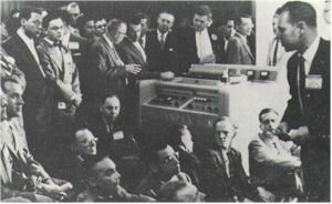
The Introduction of Videotape Recording!
|
"The NAB Convention opened the next day and the Ampex machine was the hit of the show. It was first used on-air on November 30, 1956 to time-delay "Doug Edwards and the News" for the West Coast. RCA announced a machine using the Ampex system but adding colour handling capability in 1957. Videotape was off and running!
"The role played by the SMPTE was most important, and the way it was done most impressive. In 1958, the SMPTE appointed the Video Tape Committee, with the late Howard Chinn as Chairman. It was charged with establishing standards that would ensure interchangeability of tapes among machines of various manufacturers. With full cooperation by both manufacturers, Ampex and RCA, and by all using networks, the committee worked quickly and efficiently to resolve the growing interchangeability problem in a record short time."
World Television Standards
|
Country
|
System
|
Country
|
System
|
|
Afghanistan
|
PAL
|
Madagascar
|
SECAM
|
|
Algeria
|
PAL
|
Malaysia
|
PAL
|
|
Antigua
|
NTSC
|
Malta
|
PAL
|
|
Argentina
|
PAL
|
Martinique
|
SECAM
|
|
Australia
|
PAL
|
Mauritania
|
SECAM
|
|
Austria
|
PAL
|
Mauritius
|
SECAM
|
|
Azores
|
PAL
|
Mexico
|
NTSC
|
|
Bahamas
|
NTSC
|
Midway Islands
|
NTSC
|
|
Bahrian
|
PAL
|
Monaco
|
SECAM
|
|
Bangladesh
|
PAL
|
Mongolia
|
SECAM
|
|
Barbados
|
NTSC
|
Morocco
|
SECAM
|
|
Barbuda
|
NTSC
|
Mozambique
|
PAL
|
|
Belgium
|
PAL
|
Netherland Antilles
|
NTSC
|
|
Bermuda
|
NTSC
|
New Caledonia
|
SECAM
|
|
Bolivia
|
NTSC
|
New Zealand
|
PAL
|
|
Brazil
|
PAL
|
Nicaragua
|
NTSC
|
|
Brunei
|
PAL
|
Niger
|
SECAM
|
|
Bulgaria
|
SECAM
|
Nigeria
|
PAL
|
|
Canada
|
NTSC
|
North Mariana Is.
|
NTSC
|
|
Canary Islands
|
PAL
|
Namibia
|
PAL
|
|
Chile
|
NTSC
|
Norway
|
PAL
|
|
Columbia
|
NTSC
|
Oman
|
PAL
|
|
Costa Rica
|
NTSC
|
Pakistan
|
PAL
|
|
Cuba
|
NTSC
|
Panama
|
NTSC
|
|
Cyprus
|
PAL
|
Paraguay
|
PAL
|
|
Czechoslovakia
|
SECAM
|
People's Rep. China
|
PAL
|
|
Denmark
|
PAL
|
Peru
|
NTSC
|
|
Diego Garcia
|
NTSC
|
Phillipines
|
NTSC
|
|
Djibouri
|
SECAM
|
Poland
|
SECAM
|
|
Dominican Republic
|
NTSC
|
Portugal
|
PAL
|
|
Dubai
|
PAL
|
Puerto Rico
|
NTSC
|
|
Ecuador
|
NTSC
|
Qatar
|
PAL
|
|
Egypt
|
SECAM
|
Reunion
|
SECAM
|
|
El Salvador
|
NTSC
|
American Samoa
|
NTSC
|
|
Faroe Islands
|
PAL
|
Sarawak
|
PAL
|
|
Finland
|
PAL
|
Saudi Arabia
|
SECAM
|
|
France
|
SECAM
|
Senegal
|
SECAM
|
|
Gabon
|
SECAM
|
Seychelles
|
PAL
|
|
East Germany
|
SECAM
|
Sierra Leone
|
PAL
|
|
West Germany
|
PAL
|
Singapore
|
PAL
|
|
Ghana
|
PAL
|
South Africa
|
PAL
|
|
Gibralter
|
PAL
|
Spain
|
PAL
|
|
Greece
|
SECAM
|
Sri Lanka
|
PAL
|
|
Greenland
|
PAL
|
St. Kitts
|
NTSC
|
|
Guandeloupe
|
SECAM
|
St. Pierre
|
SECAM
|
|
Guam
|
NTSC
|
Surinam
|
NTSC
|
|
Guatemala
|
NTSC
|
Swaziland
|
PAL
|
|
French Guiana
|
SECAM
|
Sweden
|
PAL
|
|
Guinea Republic
|
SECAM
|
Switzerland
|
PAL
|
|
Haiti
|
NTSC
|
Syria
|
SECAM
|
|
Holland
|
PAL
|
Tahiti
|
SECAM
|
|
Honduras
|
NTSC
|
Taiwan
|
NTSC
|
|
Hong Kong
|
PAL
|
Tanzania
|
PAL
|
|
Hungary
|
SECAM
|
Thailand
|
PAL
|
|
Iceland
|
PAL
|
Tobogo
|
NTSC
|
|
India
|
PAL
|
Togo
|
SECAM
|
|
Indonesia
|
PAL
|
Trinidad
|
NTSC
|
|
Iran
|
SECAM
|
Tunisia
|
SECAM
|
|
Iraq
|
SECAM
|
Turks & Caicos Is.
|
NTSC
|
|
Ireland
|
PAL
|
Turkey
|
PAL
|
|
Israel
|
PAL
|
Uganda
|
PAL
|
|
Italy
|
PAL
|
U. A. R.
|
PAL
|
|
Ivory Coast
|
SECAM
|
United Kingdom
|
PAL
|
|
Jamaica
|
NTSC
|
United States
|
NTSC
|
|
Japan
|
NTSC
|
Uraguay
|
PAL
|
|
Johnston Island
|
NTSC
|
U.S.S.R.
|
SECAM
|
|
Jordan
|
PAL
|
Venezuela
|
PAL
|
|
Kenya
|
PAL
|
Vietnam
|
SECAM
|
|
North Korea
|
PAL
|
Virgin Islands
|
NTSC
|
|
South Korea
|
NTSC
|
Wake Island
|
NTSC
|
|
Kuwait
|
PAL
|
Yemen_North
|
NTSC
|
|
Lebanon
|
SECAM
|
Yemen_South
|
PAL
|
|
Liberia
|
PAL
|
Yugoslavia
|
PAL
|
|
Libya
|
SECAM
|
Zaire
|
SECAM
|
|
Luxembourg
|
PAL
|
Zambia
|
PAL
|
|
Madeira
|
PAL
|
|
Did You Know?
This is a sort of "catch all" section, where I've put a lot of little video and audio hints that might be of use at some point. It is not meant to be as formal as the rest of this work - and it is meant to be expanded at whim.
If you've mounted this work in a binder, you might consider adding a few blank pages of your own here. Create your own personal "ready reference" of things important to you in your work - write in aspects of television that you find useful.
Looping Video
When dubbing from one video machine to more than one other machine, the temptation is to "loop through" the video and audio. This can be done by sending the source material to the first machine's input, followed by the second, third and so forth (using T connectors or similar devices). Or, you might send the material to the first machine's input, taking its output and sending that to the second machine's input, and so on.
Don't do either. Each loop degrades the audio, chroma, and luminance frequency response. Additionally, if you're "looping" through a Betacam machine, your subsequent machines' video will be vertically shifted down the screen.
If you must do dubs to multiple machines, use the proper routing switcher outputs or use DAs (distribution amplifiers) to send the signals to each piece of recording hardware.
Battery Belt Shooting and Charging
If you're shooting on location, and the battery belt goes dead, don't be tempted to plug it into the nearest wall outlet, while simultaneously continuing to use it. This might very well damage the charger and/or the belt. The reason is that most rechargeable batteries use a "pulse charger," and the equipment you're using requires clean, filtered direct current (DC), not the stuff from the charging unit. It's also possible you'll damage the charger unit, since it won't be connected to its proper load.
Speakers and Magnets
Magnets should never be placed close to monitors or videotape recorders. This seems like an obvious rule, but sometimes it's forgotten that speakers (and motors) have large magnets within them. If you do place magnets near this equipment, the monitor will develop a large coloured blotch (impurity), and the videotape recorder also can be affected by these large fields, leading to further troubles later.
Videotape Storage and Handling
Videotapes should always be stored vertically. Piling them up by laying them flat on shelves can result, over time, in edge binding, uneven wrap or other damage.
When handling 1" and 2" videotape, don't grab the flanges; carry the tapes by holding on to them at the centre core. This prevents mashing the flanges together, thereby crushing the tape inside.
How Head Cleaning Tapes Work
They're abrasive, that's how. Therefore, excessive or prolonged use of a head cleaning tape will cause premature wear of the tape path. They also do a lousy job of cleaning the pinch roller and capstan. There's no substitute for carefully using alcohol and proper cleaning implements (chamois for the video scanner, cotton swabs for everything else). When cleaning the scanner, always use a horizontal motion; do not move the chamois up and down, or you will misalign the heads (or perhaps snap them off completely).
Videotape Acclimatization
When using cold videotape, ensure it has had enough time to warm up. Be sure you have the tape inside the container while allowing it to warm gradually. Cold tape will almost invariably condense the moisture of the warmer air. This will cause all kinds of sticking problems when the tape is loaded into the transport. The same type of precaution goes for the videotape machine that came in from the cold.
Cleaning Equipment of Dust
Dust acts as an abrasive along the videotape path of a VTR, after it's been sucked in by the cooling fan system. It also serves as an insulator for equipment and components that were otherwise designed to be self-cooling by heatsinks or convection. Stationary equipment should be externally cleaned at least once a week to prevent build up.
Testing Microphones
Never blow into or tap a microphone element. This may ensure that it's "live," but it also may rupture the membrane of the pickup device and destroy the microphone. While we're on the subject of microphone care, never pick up a microphone (or any piece of equipment, for that matter), or drag it, by its cord. You'll rip out the conductors, causing yet another repair job.
Quartz Bulbs
When changing bulbs in lighting equipment, don't touch the glass with your fingers. The natural oil and impurities present on your hands will contaminate the glass, and drastically shorten the bulb life. Instead, use a clean piece of paper, or the sleeve that came with the bulb.
"...Because It Doesn't Know The Words"
Equipment can be susceptible to hum for many reasons, and can manifest itself as either a buzz in audio or horizontal bars running through video. The first step is to disconnect the piece of equipment from everything else - if the hum persists, then it's that particular piece of gear.
If the hum disappears, you should check your cabling. There could be insufficient shielding (or broken connectors) within the cables. Another source of hum is the ground loop. This is the state when two or more pieces of equipment connected together are powered from separate circuits with independent grounding. There can often be several volts between the two ground points; when you consider video and audio deal in millivolts, it's not surprising that this can be a problem.
"Technical power" is designed to have a separate ground from the rest of a facility. Therefore, all equipment connected to the electronics of a station should always be connected to technical power, if it is available within the building. When on location, this isn't always possible. In that case, video "hum bucking" coils or audio "isolation transformers" can be invaluable.
The electrically unsafe solution of eliminating the grounding pin on AC equipment (by cutting it off, bending it back, using two-prong extension cords or "cheaters") is not the recommended answer to hum and buzz problems.