Home Preface to Version 5.0 What's in a TV Station? Brief History and Overview Electricity 101 How It Connects Together Audio Analog Video Waveform Mons & Vectorscopes Monitors and TV Sets Cameras Lighting Switching and Video Effects Video Recording Editing for TV Film for TV Digital Video Transmission The Near Future of TV Appendices Bibliography


"One night I walked home very late and fell asleep in somebody's satellite dish. My dreams were showing up on TVs all over the world."

-- Steven Wright

Basic Principles

Up until now, we've been discussing the principles of how to produce television sound and pictures. All of this is of little use if we have no way of actually sending this program material to our viewers. This section will deal with the challenge of aiming our telecasts to the public at large.

Radio

We transmit our television programs using radio frequency (RF) waves. A look at how radio itself is sent will provide us with a solid background with which to study television broadcasting.

Radio relies on the radiation of energy from a transmitting antenna in the form of radio waves. These radio waves, travelling at the speed of light (300,000 km/sec, or 186,000 miles/sec), carry the information. When the waves arrive at a receiving antenna, a small electrical voltage is produced. After this voltage has been suitably amplified, the original information contained in the radio waves is retrieved and presented in an understandable form from a loudspeaker.

Transmission


Continuous wave transmitter (able to send Morse code)

At the heart of every transmitter is an oscillator. The oscillator produces an electrical signal of a given frequency, accurately controlled by a quartz crystal. After being amplified several thousand times, this voltage becomes the radio-frequency carrier. How this carrier is used depends upon the type of transmitter.

If applied directly to the antenna, the energy of the carrier is radiated in the form of radio waves. In early radiotelegraph communications the transmitter was keyed on and off using a telegraph key or switch. The information to be sent was transmitted by short and long bursts of radio waves that represented letters of the alphabet by the Morse code's dots and dashes. 


Samuel B. Morse

This type of transmission, known as continuous wave, is still used by amateur radio operators (hams) around the world. It can be found in modified form in high-speed teletype, facsimile, missile-guidance telemetry, and some space satellite communication. In these cases, the carrier is not switched off but shifted slightly in frequency; these shifts in frequency are decoded in the receiver.


Amplitude Modulation

In standard broadcast transmissions the speech and music are used to modulate the carrier, instead of a switch or key. One method is to superimpose the sound on the carrier by varying the amplitude of the carrier, hence the term amplitude modulation (AM). The modulating electrical signals representing audio are amplified and applied to a modulator. When the audio signals go positive, they increase the amplitude of the carrier; when they go negative, they decrease the amplitude of the carrier. The amplitude of the carrier now has superimposed on it the variation of the audio signal, with peaks and valleys dependent on the volume of the audio input. The carrier has been modulated and, after further amplification, is sent to the transmitting antenna.

The maximum modulating frequency permitted by AM broadcast stations is 5 KHz at carrier frequencies between 535 and 1,605 KHz. The strongest AM stations have a power output of 50,000 watts, and can be heard sometimes for hundreds of miles.


AM radio transmitter


Frequency Modulation

Another method of modulating the carrier is to vary its frequency. In frequency modulation (FM), during the positive portion of the audio signal the frequency of the carrier gradually increases; during the negative period the carrier frequency is decreased. The louder the sound being used for modulation, the greater will be the change in frequency. A maximum deviation of 75 KHz above and below the carrier frequency is permitted at maximum volume in FM broadcasts.

The rate at which the carrier frequency is varied is determined by the frequency of the audio signal. The maximum modulating frequency permitted by FM broadcast stations is 15 KHz at carrier frequencies between 88 and 108 MHZ. This wider carrier frequency (15 KHz for FM as opposed to 5 KHz for standard AM broadcasts) accounts for the high fidelity of FM receivers. FM stations range in power from 100 watts to 100,000 watts. They cover distances of 24-105 km (15-65 miles), because FM relies on line-of-sight transmission.

Television transmitters use both AM and FM; the video, or picture, signals are transmitted by AM and the sound by FM.

Antennas

An antenna is a wire or metal conductor used either to radiate energy from a transmitter or to pick up energy at a receiver. It is insulated from the ground and may be oriented vertically or horizontally; this is also known as its polarity. An AM broadcast antenna is vertically polarized, requiring the receiving antenna to be located vertically also, like those found on automobiles. Television and FM broadcast transmitters traditionally have used a horizontal polarization antenna, although many FM and some TV stations are now circularly (horizontally and vertically) polarized.

Wavelength

You will recall from an earlier chapter that there is a definite relationship between the frequency of a signal and what we call its wavelength. The higher a frequency you�re dealing with, the shorter its wavelength will be. Conversely, the lower the frequency, the longer the wavelength. There�s an easy to remember formula for this. It�s on the right...


Relationship between wavelengh and frequency


FM dipole antenna (note horizontal polarization)

For efficient radiation the required length of a transmitting (and receiving) dipole antenna must be half a wavelength or some multiple of a half-wavelength. Therefore, an FM station that broadcasts at 100 MHz, which has a wavelength of 3 metres (300/100, using the formula above), should have a horizontally polarized antenna 1.5 metres in length. Receiving antennas should be about the same length and placed horizontally; these sometimes take the form of "rabbit ears," or those little wire FM dipole antennas packed with your new FM receiver.

For an AM station broadcasting at 1,000 kHz (1 MHz), the half-wave transmitting antenna length should be 150 metres (300/1�2). This is a bit impractical, especially when you consider it should be mounted vertically. In this case, a quarter-wavelength antenna is often used, with the ground (earth), serving as the other quarter wavelength. With these numbers in mind, it is easy to see why AM radio transmitters require large open spaces (often fields in less densely populated areas). FM transmitters can be easily located in compact spaces such as the radome at the CN Tower.


AM transmitting field (CHUM-AM in Mississauga, Ontario Canada)


Reception

When the transmitted carrier reaches the receiving antenna, a small voltage is induced into it. This may be as small as 0.1 microvolt, but is typically 50 microvolts in a standard AM broadcast receiver. This voltage is coupled to a tunable circuit, which consists of a coil and a variable capacitor. The capacitor has a set of fixed metal plates and a set of movable plates. When the moveable ones are adjusted, the capacitance is changed, making the circuit sensitive to a different, narrow frequency range. The listener selects, by adjusting the variable capacitor, which of the many transmitted signals picked up by the antenna the receiver should reproduce.

An early method of detecting radio waves was the crystal receiver. A crystal of galena or carborundum with a "cat's whisker" provided a simple rectifier - the "cat's whisker" was a piece of fine wire delicately adjusted to rest upon the crystal in a sensitive place so that the rectification effect would take place. Once detected, the audio was left to operate the earphones. Since no external electrical power or amplifiers were used, the only source of power in the earphones was the incoming signal. Only strong signals were audible, but with a long antenna and a good ground, reception of a signal from 1,000 miles away was sometimes possible. Lately, the variable plate capacitor has been supplanted by a variable capacitance diode (varicap) or variable reactance diode (varactor). These change capacitance not mechanically, but in response to an electrical voltage at their inputs.


A simple crystal AM radio receiver (yes, this really works!)


Following the development of the triode vacuum tube, increasing selectivity (ease of separating individual stations), sensitivity (how well distant stations can be received), and audio output power was possible. The tuned-radio-frequency (TRF) process involved several stages of radio-frequency amplification before the detection stage. In early receivers each of these stages had to be separately tuned to the incoming frequency - a difficult task at the best of times. Even after single-dial tuning was achieved by ganging together the stages, the TRF was susceptible to breaking into oscillation and was unsuitable for tuning over a wide range of frequencies. The principle is still used, however, in some modern shipboard emergency receivers and fixed-frequency microwave receivers.


Simple heterodyne receiver

Practically all modern radio receivers use the heterodyne principle. The incoming modulated signal is combined with the output of a tunable local oscillator whose frequency is always a fixed amount above the incoming signal. This process, called frequency conversion or heterodyning, takes place in a mixer circuit. The output of the mixer is a radio frequency that contains the original information at the antenna. This frequency, called the intermediate frequency (IF), is typically 455 kHz in AM broadcast receivers, and 10.8 MHz in FM receivers. No matter what the frequency that the receiver is tuned to, the intermediate frequency is always the same, and it contains the information of the desired station. As a result, all further stages of radio-frequency amplification can be designed to operate at this fixed intermediate frequency - no more separate tuning knobs. After detection, audio amplifiers boost the signal to a level capable of driving a loudspeaker.

Although the method of detection differs in AM and FM receivers, the same heterodyne principle is used in each. An FM receiver, however, usually includes automatic frequency control (AFC). If the frequency of the radio's oscillator drifts from its correct value, the station will fade. To avoid this problem, a voltage is developed at the detector and fed back to the local oscillator. This voltage is used to change automatically the frequency output of the oscillator to maintain the proper intermediate frequency.

Both AM and FM receivers use automatic gain control (AGC), sometimes called automatic volume control (AVC). If a strong station is tuned in, the volume of the sound would be overwhelming if the volume control had previously been set for a weak station. This drawback is overcome by the use of negative feedback - a voltage is developed at the detector and used to reduce automatically the gain, or amplification, of the IF amplifiers.

The prime advantage of FM, in addition to its fidelity, is its immunity to electrical noise, which imposes itself on an AM signal by increasing the amplitude of the signal. This effect shows up in AM as a crackling noise. FM doesn't have this problem, because it decodes only the frequency variations, and has a limiter circuit that restricts any amplitude variations that may result from such interference.

Sidebands

When an audio signal of, say, 5 kHz is used to amplitude modulate a carrier, the output of the transmitter contains sideband frequencies in addition to the carrier frequency. The upper sideband frequencies extend to 5 kHz higher than the carrier, and the lower sideband frequencies extend to 5 kHz lower than the carrier. In normal AM broadcasts both sidebands are transmitted (and limited to 5 KHz). This requires a total bandwidth in the frequency spectrum of 10 kHz, centred on the carrier frequency. It also accounts for why we perceive AM radio as being such low fidelity - it legally has a 5 KHz upper limit on the audio frequences it can transmit.


Sidebands generated when an AM carrier is modulated


The audio signal, however, is contained in (and may be retrieved from) either the upper or lower sideband. Furthermore, the carrier itself contains no useful information. Therefore, the only part that needs to be transmitted is one of the sidebands. A system designed to do this is called "single sideband suppressed carrier" (abbreviated SSB). This is an important system because it requires only half of the bandwidth needed for ordinary AM, thus allowing more channels to be assigned in any given portion of the frequency spectrum. Also, because of the reduced power requirements, a 110 watt SSB transmitter may have a range as great as that of a 1,000 watt conventional AM transmitter. Most ham radios, commercial radiotelephones, and marine-band radios, as well as citizens band radios, use SSB systems. Receivers for such systems are more complex, however - they must reinsert the non-transmitted carrier before successful heterodyning can take place.

The concept of sidebands will be important to us when we look at how a television channel is transmitted.

Television

Transmission

When considering the transmission of television pictures, we must recall certain aspects of the video signal. The scene is scanned in about 1/30 of a second, and during that time about 280,000 picture elements must be covered. This number corresponds to scanning at the extremely high rate of 4,200,000 Hz (with twice that number of picture elements) per second.


Modern solid state television transmitter (courtesy Harris)

The transmission of the video signal at this fast a rate requires a wide channel in the radio spectrum. Each television channel in Canada occupies a frequency range of 6 MHz. This is 600 times as wide a band of frequencies as that used by an AM sound broadcast station. The 6-MHz channel used is so wide that the spectrum has room for only 68 over the air channels. They are assigned among cities and towns at sufficient geographic and frequency separations so interference between channels does not occur.

Most of the channel is used to transmit the video signal, which occupies a band of 5.45 MHz. A separate signal within the channel is used to broadcast the sound portion of a television broadcast by FM. The high quality sound that frequency modulation can achieve is sometimes not heard in television receivers, because loudspeakers small enough to fit into portable televisions cannot reproduce bass notes properly. Fortunately, this is changing as manufacturers realize there is a market for high fidelity television audio.


For the video signal to be transmitted over the air, it is carried by a carrier signal. This is an alternating current of very high frequency. On channel 2, for example, the picture carrier frequency is 55.25 MHz. This signal is generated initially by a quartz crystal oscillator at a lower frequency, which is multiplied and amplified until it reaches a power level of many kilowatts. The video signal controls one of the amplifiers, changing its power output. The amplitude modulated carrier current is directed through the transmitting antenna, designed to radiate waves in the horizontal direction.

The amplitude of the radiated wave continually changes in response to the video signal it carries. More power is radiated during the dark portions of the picture, less power during the bright portions, with maximum power output during the synchronization pulses. This is the opposite of what you would first expect, considering that baseband video's highest output is at maximum white level, and the lowest level is at sync. The advantage of this so-called "negative transmission" is that noise pulses interfering with the transmitted signal increase the carrier amplitude toward black, which makes the noise less obvious in the picture. Also, the transmitter uses less power, with lower carrier amplitudes, for pictures that are mostly white.


The "inverted" nature of television transmission


Anatomy of a typical television channel transmission

When the carrier signal is modulated, two sidebands of signal frequencies are produced, as discussed earlier. One of these, occupying a space of about 4 MHz, is transmitted in full, but only a portion, or vestige, of the other is radiated. This technique, called vestigial sideband transmission, saves a substantial amount of valuable space in the radio spectrum - otherwise, a channel almost 9 MHz in width would be required for each television signal.


Video signals transmitted in this way have the picture carrier at 1.25 MHz above the lower frequency boundary (this area being used by the smaller sideband), and extend up to 4 MHz beyond the carrier to 5.25 MHz. The colour subcarrier is placed at 3.58 MHz above the picture carrier (about 4.8 MHz within the channel). The sound carrier is placed .25 MHz (25 KHz) below the upper 6 MHz boundary; it is a conventional FM signal, with a bandwidth of about 50 KHz (+/- 25 KHz given 100% modulation).

What Are All Those Audio Signals?

Television audio�s complexity has increased somewhat since the monaural days of the 1950s. It now has a series of subcarriers, piggybacked onto the main channel�s audio, to allow us to receive such things as stereo, SAP and PRO.

Stereo is sent to the television set by using two channels - one of them is Left+Right (monaural) and the other is Left-Right (the difference between the left and right sound information.) This means that small, inexpensive sets can receive mono TV audio, while more expensive units can extract full stereo by using a matrix to decode the discrete channels.

SAP is an acronym for Second Audio Program, and was originally intended to provide a way for TV stations to broadcast in two languages at once. Many stations use SAP for descriptive video services (narration of action on the screen for the visually impaired.) Other stations rebroadcast weather information, or use it as a "barker" channel, a continuously running advertisement.

PRO is the PROfessional channel of audio. This is for internal use by TV stations for such things as cueing reporters in the field, and is sometimes used for telemetry that relays information about a station�s transmitter, back to master control.

Reception

The radio waves used in television broadcasting travel in straight lines, are intercepted when they strike any large object, and are weakened when they meet the horizon. To reach the largest possible number of viewers, therefore, the transmitting antenna must be located as high above the local terrain as possible. The primary service area of a television station thus seldom extends beyond 50 miles, although marginal reception is often possible at 100 miles if a highly sensitive receiving antenna is used.

Ghosts

When the television signal is intercepted by a nearby structure, such as a building, it is reflected in all directions, including back toward the transmitter. A receiver located between the transmitter and the reflecting structure, then, receives two signals, one directly from the transmitter as intended, the other by reflection from the structure. The reflected signal, having travelled a greater distance, arrives later than the direct signal.

Radio waves cover about 300 metres in a millionth of a second. Hence, if the reflected path is longer than the direct path by 3 km, for example, the reflected signal arrives 10 millionths of a second later than the direct signal. As noted above, the scanning of a line takes about 60 millionths of a second. So, during the scanning of each line, both the direct and the reflected signals produce images, the reflected signal producing a "ghost" of the intended image. In this example, the ghost image would be to the right of the intended image by about one-sixth of the width of the picture. Conditions in which a reflected signal exists, called multipath reception, are common in built-up city areas having many tall buildings.


How ghosts happen


Directional receiving antenna (compare with "rabbit ears")

To lessen the effect, the receiving antenna must be as high as possible and oriented so it discriminates against the reflected signal. One method of avoiding reflections is to feed many receivers by coaxial cable from a single antenna (community antenna) located high above surrounding structures, where it is free from reflected signals.

The typical outdoor receiving antenna is constructed of several parallel horizontal metal rods of different lengths spaced one behind the other. Such an array has directional properties, displaying maximum sensitivity on the line at right angles to the metal rods. For local reception, a less elaborate antenna will do, such as the extendable telescoping rods provided in portable television receivers or the use of so-called "rabbit ears."

A new signal is now being transmitted in the vertical interval (line 19) of some television stations - the ghost-cancelling reference, or GCR. It's a simple signal - just a sweep in frequency from 0 Hz to 4.2 MHz, occurring over one video line. It's only useable by new television receivers that have ghost cancelling ability. The CGR is transmitted with the regular TV picture, and is sent to the home receiver, with all of its spooky faults. A clean version of the GCR resides in the television set, and the two signals are compared. Any differences that are found between the two are used to tune filters which, in turn, cut off portions of the signal that "don't belong." The end result is a clean picture.


Ghost-cancelling reference signal (GCR)

Black and White Television Sets


Typical black and white television set

In a typical black and white television receiver, the signal from the antenna is fed to the tuner. Two channel selector switches - one for the VHF (very-high-frequency) channels 2-13 and the other for the UHF (ultra-high-frequency) channels 14-69 -are used. They connect circuits that are tuned to the desired channels and, also discriminate against signals from undesired channels. These circuits also form part of an amplifier, designed to add as little snow to the signal as possible.

The amplified signals from the desired channel are then passed to the mixer, which transposes all the signal frequencies in the channel to different values, called intermediate frequencies. The output of the tuner consists of all the signals in the desired channel, but the intermediate channel is fixed in the frequency band from 41 to 47 MHz, no matter what channel is tuned in. This is kind of like those cable television "set top" converters, that, regardless of what channel you�re watching, always convert it to "channel 3" for your TV set.

From the tuner, the 41-47 MHz channel with all picture and sound information present is passed successively through several additional amplifiers (from two to four intermediate frequency, or IF, amplifiers), which provide most of the amplification in the receiver. Their amplification is automatically adjusted, being maximum on a weak signal and less on a strong signal. So far the receiver handles the signals in the channel just like they would be received from the transmitter, except for the shift to intermediate frequencies and the amplification.

The next stage is the video detector, which removes the high frequency carrier signal and recovers the video signal. The detector also reproduces (at a lower frequency) the sound carrier and its frequency variations. The sound signal is then separated from the picture signal and passes through a frequency detector, which recovers the audio signal. This signal is amplified further and fed to the loudspeaker, where it re-creates the accompanying sound. The picture signal from the video detector is used in the normal fashion for display on the CRT of the television receiver.

Colour Television Sets

In a colour television receiver, additional circuits are provided to deal with the colour.

The only difference in the IF circuit is the importance of bandwidth for colour receivers. Remember that video frequencies around 3.58 MHz just show details in monochrome, but these frequencies are essential for colour information. Without them, there is no colour. This is why the fine tuning control on colour television sets must be tuned exactly, or else the colour disappears, along with the higher resolution.

The sound is usually taken off before the video detector in colour sets, and a separate converter is used for it, instead of taking it from the video detector. The reason that this is done is to minimize a 920 KHz beat signal that can result between the 3.58 MHz colour subcarrier and the sound carrier signal. This signal would show up as interference in the television picture.


Typical colour television receiver

The output from the video detector is sent to two places: a series of colour circuits, and a luminance output amplifier.

The luminance amplifier also serves as a cutoff filter for frequencies above 3.2 MHz, thus removing all colour information from the luminance video signal and, alas, some of the sharpness and detail. On this amplifier is where you will find your brightness and contrast controls.

In the colour recovery circuits, several things happen. First, the video detector's output is sent through a colour "band pass" filter, which leaves us with just the chrominance information - the luminance has been removed. This chroma output contains both the colour information for the picture, and the colour burst. It is then sent to a burst separator to detect the phase and level of the colour burst. This is where you�ll find your "colour" control. Now we'll have a reference for the colours within the picture, which is sent to a crystal oscillator which generates constant 3.58 MHz subcarrier of the correct phase. This oscillator�s phase can be adjusted - this is your hue control. The oscillator is used with two colour demodulators to recover the R-Y and B-Y colour difference signals. The continuous wave subcarrier is delayed by 90 degrees of phase before it enters the R-Y demodulator. The R-Y and B-Y signals are combined further to recover the G-Y signal.

All three signals are then sent to the colour picture tube's grids. There, they are combined with three luminance drive signals in the correct proportions, giving us our familiar RGB signals for driving the electron guns within the picture tube to re-create the colour television picture.

Try This At Home!

Turn on a colour TV set that is a slightly older. One that doesn�t have a whole bunch of "automatic tuning" controls on it, but instead has a fine tuning knob or pushbuttons, so you can play around. It can be hooked to cable TV or an antenna.

Now, tune in your favourite (or, perhaps, your most hated) TV channel. Play with the fine tuning controls. Notice how the colour kicks out with the high resolution detail in the picture. Eventually the sound becomes a mess, too, and may even get a sharp, 60 Hz "buzz" in it.

While you�re tuning around, look at the "Anatomy of a TV Channel" diagram in these notes and see where the sound and picture are, and notice that, at one point, the "buzz" you�re hearing is actually the sound portion of your TV set picking up the vertical sync pulses of the video. Cool!

When you�re done, PUT THE SET BACK THE WAY YOU FOUND IT - be nice to your roomies.

The Electromagnetic Spectrum

Electromagnetic radio waves use the radio spectrum. The lowest frequencies have the longest radio waves; the highest frequencies, the shortest waves.

The spectrum is divided into several frequency bands, each having characteristics peculiar to it which more or less determine the usage appropriate to that band. Each band has been assigned by international agreement at a World Administrative Radio Conference (WARC) to one or more radio services or specific usages. Sponsored by the International Telecommunication Union (an agency of the United Nations), WARCs are held to extend, review and revise frequency allocations among the various uses.

After such a conference and from time to time between conferences as Canada's needs change, Industry Canada allocates specific frequency bands to services to satisfy domestic communications requirements. A more detailed presentation of these allocations, including footnotes, is provided in Canada's Table of Frequency Allocations published by Industry Canada. It can be found online at http://strategis.ic.gc.ca/epic/internet/insmt-gst.nsf/vwGeneratedInterE/sf07031e.html

The radio spectrum is used by broadcasters, taxis, building and other construction trades, air transport, radio amateurs, marine transport, telecommunications carriers, electrical power utilities, trucking companies, police, CB operators and federal, provincial and municipal departments and agencies. It's a busy place...

Try This At Home! Listen To The World!

Find a friend with a "radio scanner" and have a listen to all the things that are sent in the radio spectrum. A good scanner can pick up most of the stuff in the spectrum chart.

Find a friend with a shortwave receiver and listen to the world! It�s neat to hear radio broadcasts from, say Luxembourg.

A good receiver can also pick up amateur radio, CB, and other neat stuff between 3 and 30 MHz on the spectrum chart.

Abridged Canadian Radio Frequency Spectrum Chart, With An Emphasis On Frequencies Used For Purposes Within The Broadcasting Industry

Frequency

Use

Cable TV Use

3-9 KHz

not allocated


9-14 KHz

long range navigation


14-535 KHz

an assortment of fixed and maritime mobile radio, radio location, radio navigation, maritime radio navigation, aeronautical mobile, aeronautical radio navigation and mobile radio


535 KHz - 1.7 MHz

AM broadcasting


1.7-54 MHz

various amateur bands, shortwave broadcasting, time signals, industrial, scientific and medical usage, CB radio, cordless phones and mobile radio


54-72 MHz

TV channels VHF 2 through 4

Ch. 2-4

72-76 MHz

Aeronautical navigation and astronomy


76-88 MHz

TV channels VHF 5, 6

Ch. 5-6

88-108 MHz

FM broadcasting (100 channels spaced 200 kHz apart)

Ch. 95-99

108-135 MHz

aeronautical navigation and communication

120-174 MHz:

Ch. 14-22

135-144 MHz

space research, land mobile radio

144-148 MHz

amateur radio

148-174 MHz

land mobile radio, marine vessel traffic, government fixed mobile, paging services

174-216 MHz

TV channels VHF 7 through 13

Ch. 7-13

216-470 MHz

an assortment of land mobile, amateur radio, Family Radio Service, government fixed and mobile radio, aeronautical, and marine radio

216-648 MHz:

Ch. 23-94

470-608 MHz

TV channels UHF 14 through 36

608-614 MHz

space operations (there is no UHF 37)

614-806 MHz

TV channels UHF 38 through 69

806-890 MHz

cellular telephones, trunked mobile radio


890 MHz - 1.2 GHz

an assortment of radio location, land mobile and paging, amateur radio, aeronautical satellite, space observation, air traffic control radar, cordless phones, paging, maritime radio


1.2 GHz

global positioning system (GPS)


1.2-1.47 GHz

an assortment of radio location, amateur radio, aeronautical satellite, space observation, air traffic control radar


1.47 GHz

digital audio broadcasting (DAB)


1.535-1.56 GHz

mobile satellite (MSAT)


1.575 GHz

global positioning system (GPS)


1.626-1.66 GHz

mobile satellite (MSAT)


1.9 GHz

personal communicatino service (PCS)


2.475 GHz

digital cordless phones, wireless LAN, microwave ovens


3.5-4.8 GHz

C band (Anik B, D, E) satellite downlinks


4.8-5.8 GHz

various radio navigation


5.8-7 GHz

C band satellite uplinks


7-8.5 GHz

various uplinks and downlinks


8.5-10.7 GHz

various radio navigation and location, including police radar


10.7-12.2 GHz

Ku band (Anik B, C, E) satellite downlinks


12.2-12.7 GHz

direct broadcast satellites (DBS)


12.7-14.5 GHz

Ku band satellite uplinks


17.5 GHz

direct broadcast satellites (DBS)


20 GHz

multimedia satellite


28 GHz

local multipoint communications systems (LMCS)


29.75 GHz

multimedia satellite


30-275 GHz

various extremely high frequency (EHF) allocations, many of them satellite usage


275-400 GHz

not allocated


The electromagnetic spectrum (graphic version)

Where Does The Cable TV Channel System Fit Into This?

Cable TV had its start in small, isolated communities that couldn't receive television very well. A handful of people decided to buy an expensive antenna, and mount it in a good spot to receive signals. To offset the cost of the system, they decided to rent the strong signals that they were receiving to some other people. That's how it started, as a community antenna system.


Twinlead (top) and coaxial cable (bottom)

Today, the round cable that comes into your home from the cable company does the same job as the old fashioned "twinlead" did in the days when everybody had their own roof-top antennas. It carries the signals from the antenna to your set. Twinlead has a problem, though: long lengths of it act like an antenna, picking up all sorts of unwanted signals (that�s why they use it to make that FM antenna that comes with your stereo) . So, for large systems with miles of cable, co-axial cable is what's used. The outside shield conductor keeps the cable company's signals in the cable, and hopefully keeps unwanted signals from the airwaves, out of the cable.


As long as the cable company has a cable from them to you, there are a lot of other signals they can send. Some come from satellites especially for cable viewers; some are produced by the cable company in their own studios. TV sets used to be built to tune in VHF and UHF channels - while all sets are "cable ready" now, they can still be set to receive the over the air spectrum. But, the regular UHF channels from 14 to 69 can't be sent down cable TV unmodified, because their high frequency energy is absorbed by the cable itself. So, that leaves us with 12 channels (the VHF dial) to accommodate 50 or so signals.

If you look at the government assignments for who can broadcast on what frequency, there's a gap between 6 and 7. There's also a huge gap between 13 and 14. The signals that the cable company sends are the same type as the ones that are broadcast, only they're confined to the cable. This means they can use the same frequencies that are occupied by aircraft, police, and taxis, and they won't interfere with those other services.

To pick up the signals resulting from this technology you'll need either a cable converter or a cable-ready television set. And, with all that converting of frequencies going on, the cable company gives you a chart.

Here's what's happening. The numbers 2 to 13 on your converter are real channels 2 through 13. The cable company probably has converted some UHF channels in your area to these, and chances are that the others are on the wrong channels, but they really occupy channels 2 through 13. Channels 14 and up aren't what they seem - 14 to 22 are the hidden 9 channels between the real 6 and 7, and 23 to 64 are a bunch from between real 13 and 14.

For those of you with 100 channel cable-ready televisions, you also have channels 65 through 94, located in, yes, UHF areas 14 through 43. But wait a minute, we said that UHF channels can't be transmitted down the cable. Well, they can, but they become increasingly noisy as you go up the band. This is why, up until lately, cable companies weren't using these frequencies. Channels 95 through 99 are located to cover completely, and go just above, the FM radio band. That's why there's nothing on those channels, either.

Try This At Home!

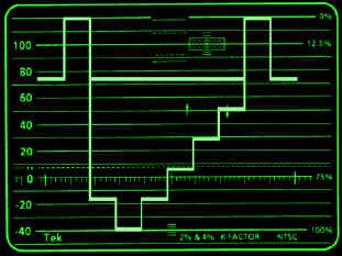
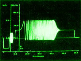
Tune your cable ready TV set to some upper channels. Notice how they get noisy, the higher you go. Now, tune way up there - into the 80s and 90s. See any other channels the cable company is using that you don�t know about? Sometimes, on Rogers, you see a graphic display called a "spectrum analyzer" that looks at the relative levels of all the channels in the system!

Don't Touch That Dial: Digital Cable, Telcos, MMDS, LMCS, DBS

Over-the-air terrestrial transmission and standard analog cable TV no longer have a monopoly on the way to get television signals into your home. There are several other systems. Keep a watch for:

Digital Cable TV

Brought to you by your local cable company, it�s a digital multi-channel version of what we know in the analog world, using the same cable, but getting around that coaxial cable frequency absorption problem by encoding the television channels digitally. It requires a set-top box to decode the digital signals back into analog NTSC for you to enjoy.

Video By Telephone

Your local telephone company, for years, was working overtime to perfect a system that will bring video to your place via phone lines (plain old telephone service, or POTS), or a modification thereof. Not much news lately, but you never know. Stay tuned.

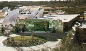
Multichannel Multipoint Distribution Systems (MMDS)

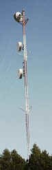
On August 6, 1997, Teleglobe Inc. won a license to begin a service called Look TV in the Toronto area. It�s based on a system called MMDS. It works in the 2.5 to 2.686 GHz range and can do a line of sight transmission of 40 to 50 kilometres. The main antenna is on the CN Tower, but there are some booster/repeater towers around town, so if you can see any of them, you can subscribe to MMDS distribution. The repeaters increase the coverage by receiving the main signal and retransmitting it further afield. MMDS uses a 30 cm square flat antenna, and no cables. The MMDS system is comparably priced to regular cable TV subscription rates, after an installation fee. Look TV now has services in Southern Ontario, Ottawa, Montreal, Trois-Rivieres, and Quebec City. In Manitoba, a similar system called SkyCable already exists and works on the same principles.

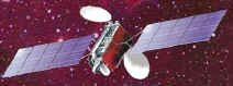
Direct Broadcast Satellite (DBS)

Various pizza-sized dish "direct to home" satellite reception alternatives, that have got off to a slow start in Canada (but are picking up steam quickly) and have done well in the United States. More on these later in this chapter.

Wireless Mics, IFBs, Headsets and Interference


Typical wireless microphone system: beltpack, receiver, transmitter adapter, antennas, self-contained handheld microphone (courtesy Electrosonic)

Wireless audio and video gear allows us to shoot in any area, at any time. Wireless microphones, wireless IFBs and intercom sets allow freedom of movement for various people. Wireless video transmission equipment allows us to shoot on convention floors and other locations where stringing cable would be prohibitive.

Once feared as exotic and temperamental, wireless mics have become tame over the past ten years or so. The increase in mobile cameras and recorders has ensured a solid place for them in the future of broadcasting. This equipment is very handy, but causes some problems since it can cause interference, and be interfered with. Let the user beware! One should always have a backup (wired) system, in case of unforeseen difficulties.


Especially with VHF body-pack transmitters, it's a good idea to make sure the antenna on the talent is vertical. If the receivers' antennas are vertical, the transmitters' antennas should also be vertical - talent may have to be discouraged from coiling up a VHF antenna and tucking it neatly away. However, a flexible wire whip antenna is still preferred to a more rigid "rubber duck" antenna, since the human body is largely composed of water and salt (conductive), and it tends to detune the stiffer type of antenna.


Diversity transmission systems

To help eliminate the effects of RF dropout as the talent moves around the shooting environment, diversity reception has been developed. Today, many systems use two antennas with two receivers - a special switch goes back and forth between receivers taking the stronger signal, and ignoring the weaker. Some systems mix the two receivers, instead of simply switch from one to another. Another system involves checking the received RF phase between two antennas - the phase of the second one is constantly adjusted to complement the signal from the first. This unit needs only one receiver and one audio output.

Wireless audio gear operates on various VHF and UHF frequencies between television channel 7 and 13. These units are also used on location shoots to free talent of their audio umbilical cord.


Wireless microphone technology, circa 1936 (courtesy Popular Communications)

Some stations have taken wireless equipment usage to a new high. As of this writing there are transmitters on various frequencies between 174-216 MHz (interleaved neatly between and through channels 7 through 13); 470-608 MHz (interleaved between and through channels 14 through 36); 614-806 MHz (interleaved between and through channels 38 through 69) and 902-916 MHz (a new band for microphones). These frequencies are used for wireless microphones, IFBs, and floor director headsets.

Wireless video transmission gear operates in the 2 GHz range.

In case you feel that wireless RF microphones are a relatively new idea, check out the accompanying picture from an actual VHF system, circa 1936. The transmitter put out 1/5 watt, at 270 MHz. Its receiver was in the radio truck, 30 to 40 feet away. Very dashing...

Satellites

An artificial satellite, in general terms, is an object placed into orbit around the Earth for scientific research, Earth applications, or military reconnaissance.

How They Stay Up There

A theoretical object, at just above ground level (about 270 km - to avoid mountains), will neither crash into the ground, nor fly off into space when it's given a horizontal velocity of approximately 27,860 km/h. This is because, at this velocity, the Earth's surface curves away from the object as fast as gravity pulls it downward. This theoretical object would circle the globe, at the equator (39,843 km), in about an hour and a half.


Anik C/D

As the altitude of the satellite increases, its velocity can decrease. Its period - the time the satellite takes to circle the Earth - increases

Based on that, if we were to take our satellite and move it up to 35,840 km above the Earth, it would have a period of 24 hours (the same amount of time as the Earth's rotation). It would have a velocity of only 11,050 km/h. A satellite like this is called a synchronous satellite. If such a satellite orbits above the equator, it is termed geostationary because it will remain at the same point above the Earth's surface.

How We Figured This Out


Anik E1, E2

If you are interested in a fairly complete history of Canadian and international satellite progress, please refer to the Appendix.

What's In A Satellite?

All artificial satellites have certain features in common. They include:

radar for altitude measurements

sensors such as optical devices in observation satellites

receivers and transmitters in communications satellites

stable radio signal sources in navigation satellites

antennas to receive and transmit signals

solar cells to generate power from the sun, and storage batteries are used for the periods when the satellite is blocked from the sun by the Earth. These batteries in turn are recharged by the solar cells

in special cases, nuclear power sources are utilized

attitude control equipment is needed to keep the satellite in its desired orbit and, in some cases, to point the antennas or sensors properly

telemetry encoders measure voltages, currents, temperatures, and other parameters describing the health of the equipment and relay this information to Earth


Galaxy 601 (DBS 1, 2)

Why Do We Use Them?


Typical microwave tower

Most long-distance radio communication across land is sent via microwave relay towers. These towers, 30 to 60 metres high, are typically spaced 30 to 50 km apart, and about 100 of them are needed to cross the country. Thus microwave relay towers are impractical for transoceanic communications.

The satellite serves as a sort of tall microwave tower to permit direct transmission between stations. But, unlike a microwave link or a cable, it can interconnect any number of stations that are included within the antenna beams of the satellite rather than simply the two ends of the microwave link. The use of a satellite repeater was first proposed by Arthur C. Clarke in the October 1945 issue of Wireless World.

Who's Up There?

For a complete explanation of the various kinds of satellites, their altitudes and uses, please refer to the Appendix.

Okay Then, Can You At Least Tell Me What Geosynchronous Satellites Are Available in North America?

Sure. Click on the picture for a large detailed view of all satellites we can see from North America. The picture is mine (and is copyrighted, so if you use it, give me and this website credit), but the raw data is from LyngSat (www.lyngsat.com) and is accurate as of August, 2003. But the satellite picture is changing all the time, so this diagram is subject to change without notice.

DBS

Direct Broadcast Satellite...the Death Star...

You heard all about it through the 1990s. The launch of Hughes Galaxy 601 (commonly known in the industry as DBS-1) in December of 1993 signalled the beginning of a new era in entertainment distribution. This service now beams more than 225 channels of audio and video programming to 18-inch satellite dishes installed in homes across the 48 contiguous United States (and a few Canadian provinces, as well.)


DirecTv, Castle Rock, Colorado


Hughes' DirecTv's broadcast centre is in Castle Rock, Colorado (about 30 miles south of Denver) and uses the DBS-1 and DBS-2 satellites. It was the first fully serial digital transmission facility capable of broadcasting more than 200 simultaneous channels of programming. These include: twenty-seven (27) movie channels, twenty-four (24) "family and children" channels, thirty-three (33) arts and entertainment channels, eighteen (18) news and information channels, twenty-five (25) regional sports networks, fifty-five (55) pay-per-view selections, and three dozen (36) audio-only music channels (featuring 24 hour background music with no commercials or talk).

If you look at the back of a DBS receiver, there's another glimpse of the future there. You'll find a low-speed data port, perhaps for some type of data transmission service. There's also a wide-band port, for HDTV.

There are only two DBS players in the United States: DirectTv and EchoStar (Dish Network.)

Direct Broadcast - The Canadian Story

While in the United States, DBS dishes and receivers were being installed into homes for the first time in October, 1994, Canadians waited for an equivalent system in this country. Some couldn�t wait - an estimated 200,000 Canadian homes had so-called "grey market" DBS dishes that received U.S. services. As this is, strictly speaking, illegal, their subscriptions had to be forwarded from a valid United States address (for a slight monthly fee to the third-party subscription dealer, of course.)

The Canadian domestic DBS system had been held up for several reasons. The CRTC, at one time, tried to block a direct-to-home service. Finally, a single distributor consortium (made up of cable companies and programming distributors) was granted a license without the usual hearing process. ExpressVu was formed, and the Commission was insistent that it use a technology that was incompatible with the U.S. distributors for fear that a similarity in systems would help persuade Canadian system owners to switch to a U.S. company. The federal government intervened after a successful appeal by a rival organization, Power DirecTv Inc. Hearings were held, and the competing systems were given the go-ahead to try their luck.

Their luck has not been good.

Power DirecTv�s plan crumbled under the weight of the CRTC�s imposed regulations.

On March 26, 1996, Anik E1 was thrown off by a wave of high energy solar particles, permanently crippling the satellite and critically reducing the Canadian satellite transponder space for any kind of direct to home system.

Finally, the first subscriber signed up for AlphaStar Canada�s system in mid-March, 1997 - almost two and half years after the U.S. services began sending their signals. AlphaStar then filed for Chapter 11 in the United States on May 27th, followed by its parent company Tee-Comm going into receivership on June 4th. Finally, on August 7, 1997 at 3:00 a.m., all AlphaStar transmissions were cut off, a short five months after they had signed on.

StarChoice (since taken over by Rogers and Shaw) started its service on April 28, 1997. ExpressVu (now Bell ExpressVu) launched its system on September 10, 1997, after having bought the subscriber base of AlphaStar. As of summer, 2003, each of these services (the two remaining in Canada) have over 300 channels of video and audio on their systems, and now have a combined subscriber base of over 2 million Canadians - ExpressVu has approximately 1.3 million, and StarChoice has about 800 thousand.


Telesat's uplink centre, Toronto

Telesat won approval on April 3, 1997 to build and fly a DTH satellite (called Nimiq) and it was launched on May 21, 1999. It features 32 Ku-band transponders, each able to carry seven or eight signals each - that's about 256 digital channels on the bird. Bell ExpressVu and StarChoice had been operating for about two years on the Anik E series of analog satellites. Both companies haved moved to the new Telesat bird; ExpressVu also has some channels on its sister Nimiq 2, launched December 30, 2002.


Nimiq 1

World Television Standards

Undoubtedly the reader will be familiar, at least in passing, with the terms NTSC, PAL and SECAM. These three acronyms represent the types of colour television systems used in the world. Such technical factors as line number, field rate, video bandwidth, modulation technique and sound carrier frequency make up the differences within the three main methods. There are also several variations within each process.

Similarities

If you understand the NTSC system, you have the basis for understanding PAL and SECAM. All three systems, for example, use the RGB principle of picking up the colour picture information from a scene. They also all include the idea of being compatible with previously invented monochrome standards. Therefore, the luminance information is chosen in all approaches to occupy the wide-band portion of the channel and to convey the brightness as well as the detail information. Also, the chrominance information, in all systems, is superimposed upon this luminance signal.


All world television systems: encode RGB; are compatible with the existing black and white systems; and superimpose chroma on luminance


For a complete analysis of the encoding systems of the three major television standards, and an understanding of the various scanning rates used in conjunction with these systems, please refer to the Appendix.

Standards Converters

The fact that there are at least eight major TV standards in the world today is a barrier to the simple interchange of foreign programs and sporting events. Fortunately, these difficulties can be solved using standards converters.

Standards conversion is the process of changing the line and/or field rate structure of the TV signal. Ideally, this should be done with a minimum of what's called "judder", which is a motion artifact wherein smooth motion is portrayed in an irregular, shuddering way. Standards conversion is best accomplished in the digital domain. The advantage of digital processing revolves around the ability to use digital processing of multiple fields of video, along with an ever-increasing availability of computing power, allowing more complex conversion formulas. Converters analyze incoming video fields at one sample rate and create intermediate fields through interpolation, at the sample rate of the output standard. It's the job of motion compensation formulas to compute where an object will be in the next field. If this is done successfully, the output displays motion smoothly, with a minimum of artifacts.

Sports programming is frequently used to test and demonstrate standards converters. Interestingly, our own sport of hockey features fast pans and the small, fast puck, as well as high contrast, stark images that will reveal any judder.

Master Control


DirecTv Master Control

When all of the diverse elements of the daily program schedule come together, there has to be some way of integrating them in a connected way. That is where master control comes in. Master control operators (and their equipment) are responsible for the final output and look of the station. Their varied tasks include:

rolling in various pre-recorded programming, either on videotape or film,

taking live shows (such as news programming and flashes) at the proper time,

inserting at the proper time appropriate bumpers and commercial breaks, logging those commercials,

adding station IDs and audio carts when required,

ensuring that all programming is integrated into the day as per the directions of the programming and traffic departments,

and making sure that the transmission of the station is always flawless.

It is a sometimes hectic series of proceedings, involving minute-by-minute scrutiny of programs, cue sheets, and technical quality of all material. Paper logs of all commercial and promotional content have to be accurate, as required by the CRTC. There are also videotape logs to be maintained, which are kept in a library containing every minute of broadcasting for the last two months.

Master Control Switcher

The heart of the master control operator's equipment is the switcher, which can perform cuts, dissolves, and keys like a production switcher. There is one significant difference, however - the MCR switcher also has the ability to take audio from any of the sources selected, and is therefore called an "audio follow" switcher.

In addition to the regular program audio, the MCR operator (or "MCO") has the capability of sending out additional tape or digital cartridge material either to replace the existing audio completely, or mixing it over the continuing source. This is done by lowering the level of the program material and is called "voice over" mode.

The keyer on the switcher is generally used to superimpose station identification information over program material, or other statistics such as the time of day.


Typical master control switcher (courtesy Dynatech) (click on the picture for a bigger view)

With all of this information and technical detail to watch over, master control operations are beginning to computerize. The computer remembers and activates transitions sequences. It also cues, rolls, and stops film projectors and VTRs, and calls up any number of slides from the stillstore system.

The development of MCR switchers is going in two directions. One can have the switcher perform more and more visual tricks. Or, it can be kept simple enough so that the operator does not have to climb all over it to reach everything, or take a computer course to use it.

Things To Think About

Our television transmission system uses radio waves, travelling at the speed of light. Radio waves can be modulated in various ways, and we use both AM and FM in television transmission.

For best results, antennas should be of a certain length and polarity, and there is a tried and true process for modulating and demodulating transmissions. The television channel has within it video, and multiple channels of audio.

The electromagnetic spectrum has been carefully carved up by the power that be so that everybody gets to use what they need and not interfere with one another. The dissection is intricate, and you should be familiar with some of the fundamental slices. Every year, somebody comes up with another use for the electromagnetic spectrum - different ways of transmitting signals to the home, wireless mics, and so on.

Satellites are 20th-century wonders. They have some basic components that make them work well, and more capacity is now available with digital compression.

There are three major world television colour standards, and even though they differ widely, they have some commonality between them. To go from one format to another, we use scans conversions.

Master control is the place we�ve all been waiting for. Without it, all of our hard work never makes it to air. Be conscious of the importance of this facility, and some of the things this environment does to keep us in the skies.