It was possible to make a record of a show, a film shot from the screen of a broadcast quality monitor, called a kinescope recording. These recordings were frequently made for use by stations beyond the reach of cable or microwave interconnections with the networks. Because kinescope recordings were expensive and of poor quality, almost from the start of television, engineers searched for a way to record video images on magnetic tape.
In the 1950s, audio tape recordings were widely used on radio, and tape recorders were becoming popular on the consumer market. It was logical that if signals representing audio could be stored on tape, their video counterparts also could be recorded. The problem was that the video signal was far more complex, and the frequencies involved were much higher than in audio.
Analog Videotape Recording Principles
Getting The Signal On Tape
We've got a real problem when we try to record full blown video using a method similar to what we do with audio. Basic physics states that the highest frequency you can record on magnetic tape is determined by two things. One is how fast the tape travels by the head, and the other is how narrow the head gap is (the space between the two poles on a recording head).
The formula is
Fmax = Vtape / 2 x Wgap.
|

Why there is a limit to how high a frequency you can record
|
This means that the maximum frequency you can record is equal to the velocity of the tape as is passes by the head, divided by twice the width of the tape head's gap.
In audio, the highest frequency that has to be recorded is about 20,000 cycles per second. This means that, at 15 inches per second tape speed, you'll need a head gap of .000375 of an inch (20,000 = 15 / 2 x Wgap, or Wgap = 15 / 2 x 20000 = .000375.) This was totally manageable in the 1950s, and made for excellent quality audio recordings. In fact, head gaps could be made as small as .00006 inches (about 1/16000 of an inch wide), meaning audio recordings as slow as 3 3/4 inches per second sounded fine.
But, we digress. Just keep in mind that .00006 of an inch head gap width.
|
|
The video signal has frequencies up to 4.2 million Hz in it. Using our now well-worn formula, we plug in the numbers, and come up with a tape speed of 504 inches per second! (4200000 Hz x 2 x .00006 gap width = 504 inches per second.) A half hour recording at this speed would require 75,600 feet of videotape (a little more than 14 miles). This just won't do. But we tried anyway:
November, 1951: The Electronics Division of Bing Crosby Enterprises demonstrated a black and white videotape recorder with twelve fixed recording heads. Using high speed head switching, 1" tape and 100 inches per second tape speed, a 1.7 MHz recording is made on reels that hold 16 minutes of program material - and 8000 feet of tape.
1952: The BBC showed off VERA (Vision Electronic Recording Apparatus), which uses two video tracks, tape speeds of 200 inches per second - and quite low resolution.
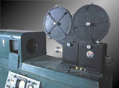
December, 1953: RCA displayed their black and white system - one continuous video track, with a 17" reel of 1/4" wide tape, moving at 360 inches per second. Later that month, RCA proved that they could perform the same feat in colour. They used a 17" reel of �" wide tape, three video tracks (R, G, and B) along with a sync pulse track, still running at 360 inches per second, and a recording time of...four minutes.
|
BBC�s VERA, 1952
RCA prototype VTR, 1953
|
How The Quad Did It
|
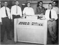
The Ampex guys, 1956
|
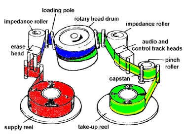
The breakthrough finally came in 1956 from a team of engineers working at Ampex. They solved the problem by mounting the recording heads on a drum that revolved at high speed (14,400 rpm), impressing the signal crosswise on the tape. The actual head-to-tape speed was very high, but the tape transport moved the tape at a relatively slow speed. This was the "quad," so called because of its use of four recording heads. It used tape 2 inches wide. |
How The Quad Works (and, why we care...)
|
Here's a little nitty-gritty on what the guys at Ampex designed into their machine.
In one second, the head drum rotates 240 times, placing 960 short tracks on the videotape. The tape is 2" wide, but room is left for audio, control track, and blank, separating "guard bands" between all of the tracks. Therefore, each video track is about 1 4/5 inches long. To allow uninterrupted output from the switched heads, only 1 5/8 inches is used for fresh video - the rest is overlap from the previous track�s video.
If we do the math on the Ampex system, we find out that the effective tape-to-head speed is 1560 inches per second. (960 tracks per second x 1.625 inches = 1560 i.p.s.) Using our familiar formula (1560 / 2 x .00006 = 13,000,000), this means we can record a frequency of up to 13 MHz - lots of room for our 4.2 MHz video signal. It's not quite that simple, however.
|

Track layout on a 2" quadruplex videotape machine
|
|
Why we don�t record baseband video onto the tape directly
|
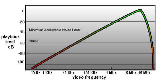
The next problem is one of the strength of a signal relative to its frequency. If we try to record a full-response signal directly on tape, we find out that the higher the frequency of a recorded signal, the greater the playback output from the tape. Conversely, the lower the frequency, the lower the playback output.
This causes us grief because we are trying to put on videotape a signal between 30 Hz and 4,200,000 Hz. This is a 140,000:1 ratio. And that, in turn, means that the playback voltage at 30 Hz will be 1/140,000 as strong as that at 4.2 MHz. Expressed as dB (like audio), this ends up being a range from lowest to highest of about 103 dB. That�s like trying to record a quiet conversation and an airport runway at the same time. This is not good. What to do?
|
Using a super equalizer to hold down the higher frequencies (thereby making the frequencies more "even" to one another) is one idea. Unfortunately, even today (let alone in 1956), most amplifiers and equalizers have electronic noise in them below about 60 dB - that's a long way from our 103 dB required range. With this method, all of our low frequencies would be hopelessly lost in the noise.
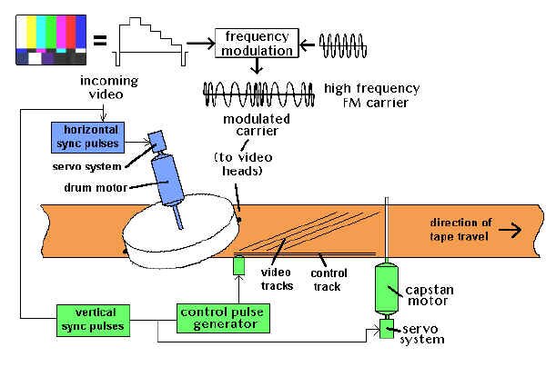
| The solution lies in a device called a modulator. A modulator is a sort of valve. One signal, called a carrier, is sent into the modulator. A second signal, the modulating one, varies a parameter of the carrier - either (1) its level (or "amplitude") or (2) its (otherwise constant) frequency. The output is either an "amplitude modulation" or a "frequency modulation" of the input signal; known as AM and FM to most radio listeners. |
Types of modulation (A.M. and F.M.)
|
 |
What we're going to use to solve our problem is frequency modulation. A carrier of 8.6 MHz is modulated by the incoming video (which may be up to 4.2 MHz). The modulator output will vary from 4.4 MHz to 12.8 MHz. (8.6 - 4.2 = 4.4 MHz; 8.6 + 4.4 = 12.8 MHz.) Within these fluctuations is a replica of the program video.
What's important to us is the ratio of the highest to lowest frequencies on the tape. That's now about 3:1 (12.8 : 4.4). This is a little less than a 10 dB difference. Any noise in any electronic amplifiers we use will be away back at -60 dB; an excellent safety margin.
Now, to use this modulated system, we'll need to be able to record up to 13 MHz of information on our VTR. With the quad system, and its effective tape to head speed of 1560 inches, we have that recording capacity. What a coincidence...
|
Getting The Signal Off The Tape
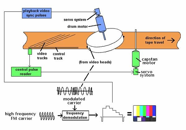
The demodulator (If there was a modulator you just had to know there'd be a demodulator!) has the reverse function of the modulator - it takes the high frequency signal from the tape and retrieves the video signal from it. This fundamental video signal is then put through various processing circuitry to make it stable and to adjust its levels, at which point it is like any other video source.
Of course, it's more complicated than that. We've glossed over all kinds of things like...
Servos and Time Base Correctors
Keeping Track of the Tracks
When a videotape is recorded, there must be a way of letting the videotape recorder know later on just when and where the video tracks were laid down, so they may be played back reliably. In addition, the motor spinning our rotating video heads (the head drum motor) and the motor actually pulling the tape through the transport (the capstan motor) must be kept running at a very constant, identifiable speed, referenced to the incoming video. We do it with a servo.
Drum and Capstan Servos
|
A servo, in general terms, is an automatic control mechanism in which the output of a device is compared with a stable input reference, so corrections can be made.
Consider the following predicament. You've been chosen to keep the speed of a fan motor constant. To do that, we've supplied you with some equipment - a knob to speed up and slow down the fan, and a little counter that's attached to the fan's motor shaft. Every second, the counter starts counting the revolutions of the fan motor. Your job is to keep the counter always at 100 counts per second - no more, no less.
In the first second, the counter counts up to 102; you turn the speed control down a little bit, to slow down the fan. In the next second, the counter only counts up to 97 (you went too far); you turn up the knob a little bit. In the next second, the counter is up to 99; you turn it up a tiny bit more. The subsequent count says you're up to 101; you back off the knob a little bit. And so on...
You're a servo. You're continually comparing the speed of the fan to a constant (100), and adjusting the speed to try and match it. Now get rid of the knob, the little counter display, and your hand... and do it all electronically. That's an electronic servo.
|

"The human servo"
|
The Drum Servo
The drum servo is trying to keep a constant speed for the video heads as they go across the videotape. During record, it looks at the incoming video's horizontal sync pulses and ensures that the VTR lays down the proper tracks for each frame of video. During playback, the drum servo can either lock to the playback video itself, or an external reference from a central sync generator (within the broadcast facility), and ensures that it plays back the correct video tracks to reproduce the video.
The Capstan Servo
The capstan servo, on the other hand, is trying to ensure that the tape is being pulled through the videotape recorder at a very constant speed. During record, the capstan motor runs at a certain speed, which is compared to the timing of the incoming video's vertical sync pulses. While this is going on, a control track is being laid down on the video tape. This is a pulse for every frame of video - about 30 pulses a second. On playback, the capstan servo looks at the control track and makes sure that the tape is being played back at exactly the right speed. In broadcast VTRs, this is often referenced to the station's external vertical sync pulses.
The control track signal is also a basis for setting up the tape's position relative to the video heads' ability to pick up the tracks recorded on the tape. The speed is adjusted during the "lock up" period just after pressing the play button, so the video tracks line up precisely with the video heads sweeping by. This process is known as "tracking", and it usually takes a couple of seconds to take hold. That's why, when you push play on a VTR, the picture is a little unstable for a couple of seconds - the VTR's servos are getting their act together. And that's why, in a production environment, we roll a VTR a few seconds before we need to take it to air - to allow for the VTR lock-up time.
Videotape recording basics
Videotape playback basics
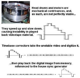
Time Base Correction
All VTRs are mechanical devices, and there is a limit to the timing accuracy on playback that can be achieved. The limit is set by the mechanical accuracy of headwheel bearings and motors, and a certain minimum variation in tape quality along the length and width of the tape. Also, gradual and sudden variations of tape guide adjustment and tape path during extended use may cause instability. Time base correctors are used to take out the remaining mechanical jitters in videotape playback so that the signal is stable for broadcast use.
AMTEC |
The first quad VTRs had two devices within them. The AMTEC (Ampex Tape Error Corrector), the first analog timebase corrector, was essentially a series of electronically variable delay lines used to compensate for the playback timebase error. As the head drum speed deviations were detected, a signal representing these errors would be sent to the AMTEC, and the video signal would be delayed as necessary to compensate for the instability. The COLORTEC was later designed for less major errors, to provide a stable colour playback signal. |
COLORTEC |

Modern timebase corrector (courtesy DPS)
|
How TBCs work
|
Today, modern timebase correctors not only allow us to compensate for timebase errors, but, since they're digitizing the video anyway (usually a frame at a time), allow us to adjust video, black and chroma levels, hue. They also frequently offer special effects like strobing and freezing of frames and fields. Finally, this correction technology is used in not only composite video, but component and S-VHS video formats as well. |
Analog VTR Formats
| Up until now, we've been concentrating pretty much on an outdated videotape format - 2" quad. Why? Because the quad was the venerable workhorse of television videotape for the first twenty years, until the mid-1970s. But there's more to it than that. |
Quad head drum
|
|
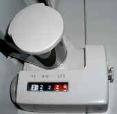
Quad tape timer/counter
|
A 2" VTR embodies all the principles used in modern helical scan machines (which have replaced the quad for the last 25 years), but in ways that are easy for all to see. Indeed, each component and section of a quad can be physically removed and studied further. By contrast, modern VTRs are often highly centralized marvels of construction; often more than one subsystem will be on a single printed circuit board - or even within one integrated circuit chip. |
| Much has been said for the "hands-on" approach to learning about videotape technology, but in fact, so much of this background information is seldom used because of the comparable high reliability of today's equipment, and the relative lack of operator adjustments. There are hardly any line up controls on the front panels of such equipment, except input and output level controls and tracking adjustments. Even these can often be placed in "automatic" or preset positions. |
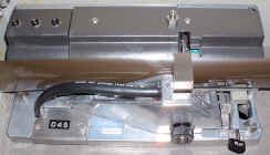
Quad head assembly
|
|
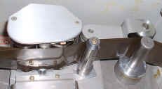
Quad audio head assembly, capstan & pinch roller
|
With this in mind, it is now time to leave nostalgia and history behind us, and take a look at the myriad formats and features available to us today. The following comparisons are sometimes a little subjective, but shed some light on the relative merits of each format, when considered within a broadcasting environment. |
1" Type C
| This format, first appearing in 1978, was the first machine to add special effect capabilities (e.g., still frame, slow motion, and the ability to see pictures while shuttling the tape at high speed) that were not possible with the 2" quad VTR. Also, the 1" VTR introduced the use of automatic scan tracking (which we'll discuss later on). The professional industry's workhorse from the late 1970s to the early 1990s, this format is now obsolete. 1-inch offered excellent quality, flawed only by a build up of noise on successive generations. |
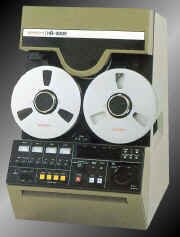
1" VTR
|
U-matic (3/4")
|
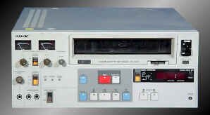
U-matic VTR
|
Initially introduced as a home recording format in the early 1970s (consumers found it too big and clunky, with a short recording time), this was the first helical format to be widely accepted and was ultimately to find its niche in the ENG (electronic news gathering) and industrial markets. U-matic, like 1" open reel, has become obsolete because there are so many other higher quality recording formats with smaller cassette sizes and greater reliability. |
Component
| Betacam was the first of the small format machines intended for ENG and EFP (electronic field production) use. Introduced in the early 1980s, its use of an upgraded consumer format cassette was the notable feature, as well as its being the first professional component recorder - the luminance and chroma signals are recorded on separate tracks allowing each of the two signal channels to be optimized for their particular requirements. Many stations find that Betacam is perfectly useable for general purpose on-air use, including program and commercial playbacks. The overall look is very slightly noisy because of the amount of signal processing going on, but probably below the threshold of visibility for most people. When used in a completely component environment, the results are very good. Betacam�s close relation, Betacam SP, uses a metal type tape for higher quality video reproduction. There are lots of these machines in the field, so it�s likely that they will be around for some time. |
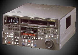
Betacam VTR
|
The M format is based on an upgrade of the consumer VHS system, is also a component system, but its two chroma signals are recorded on the same track using a frequency multiplex system. The M-II format was developed to increase the play time and bandwidth of the M format. Higher coercivity tape is used, along with a slower tape speed. In M-II, time compression multiplexing is used on the chroma signals, like Betacam.
Consumer Formats
Betamax
|
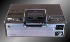
Betamax consumer VCR
|
Not to be confused with Betacam (the broadcast format), this was the first standardized consumer video format and used a composite recording system. Later Betamax versions introduced the concept of "HiFi" audio using an FM subcarrier. Now obsolete, but an important contributor to home recording history. |
VHS and S-VHS
This system came out shortly after the Betamax system and, despite its poorer picture quality, outsold Betamax due to longer playing times on the cassettes. The "HiFi" version of this machine uses a recording system for its audio in which a long wavelength FM carrier is recorded under the high frequency FM video carrier.
| The S-VHS system uses a high coercivity tape, and the maximum video FM carrier frequency was increased, resulting in picture resolution improvement. For broadcast work, its main problems are: lots of artifacts induced by signal processing, and low signal-to-noise ratio. Colour "smears" down the screen, and there is a definite "haze" over the image because of the noise reduction circuitry. Even then, noise continues to be a problem due to the very slow tape speeds. For "first generation" work, S-VHS may be indeed a good choice. Once you start going down a few, however, the noise and other artifacts quickly make S-VHS rather unacceptable for broadcast work, although industrial video suites abound. With the proliferation of inexpensive and compact MiniDV digital camcorder and playback VTRs, S-VHS has now become an obsolete format. |
S-VHS VTR
|
8mm and Hi8
The 8mm format was the first time a consumer video machine made that use of an "imbedded" tracking servo rather than a longitudinal control track. This allows the use of a very slow tape speed, metal evaporated tape, and a small cassette size. You'll also notice that there is no tracking knob on any 8mm format machine. HiFi audio is available through an FM subcarrier recording system, with PCM digital audio as an option built into the format specifications. Even in the Hi8 format, frequency response rolls off fairly quickly above 3 MHz, though some artificial peaking is added to give the impression that things are not that bad. For camcorder work however it is ideal, with one of the best format size/picture quality ratios, for an older analog format. It�s still in use as a consumer camcorder format.
Helical Scan Recorders In Depth
|
Typical cassette loading (VHS)
Omega wrap
180 Wrap
|
All of the above listed formats have one thing in common - they're all called "helical wrap" machines. One method of achieving the necessary head-to-tape speed for recording involves wrapping the tape around a revolving drum-shaped scanner in the form of a helix.
That's A Wrap
Omega
Viewed from above, the tape path resembles the Greek letter omega, and thus the wrap's designation. It places the entry and exit guides as close together as possible; if they're close enough, the entire active video picture can be recorded by a single head. There will be a small "dropout," however, as the head leaves the tape between the two guides. This is timed to occur during the vertical interval. Example of this wrap: 1" C format.
180 Degree
The tape only contacts about 50% of the drum surface, therefore two heads are required to record all the video. This wrap is easy to mechanize, and there is no dropout, since one head is always in contact with the tape. Example of this wrap: almost every analog cassette format.
|
Slow Motion and Stop Motion
|
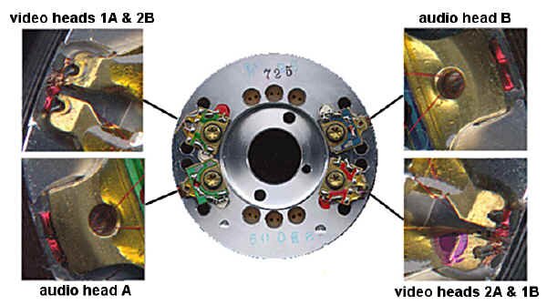
Let's consider for a moment how a helical scan machine actually records its information on the videotape. A typical helical format machine, due to its wrap, lays out its video tracks on a diagonal, across the width of the tape. There's space left at the top for two longitudinal audio tracks, and some room at the bottom: for the control track, some little sync head recordings, (on some formats such at 1" type C) and a third audio track usually used to record time code information.
All helical scan VTRs record a pattern very similar to this one; there will be some more illustrations later on to show some differences, but the basic concepts of a diagonal video track and some longitudinal tracks remains the same throughout most of the formats.
|
Typical helical scan track layout (1" VTR)
|
|
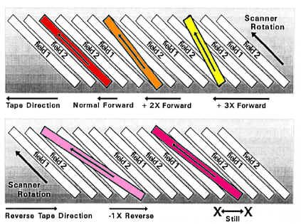
Head drum scan angle changes with stopped or variable speed helical scan VTRs
|
Helical systems can be used for stop motion playback, by simply stopping the tape and keeping the head rotating at field rate; theoretically, the video playback head would just keep scanning the same track over and over again. There's a hitch, though - the scan angle (and its length) is now slightly different since the tape is stopped instead of moving. After all, the tape moved a small amount during the original field recording, and now we're trying to reproduce the same video track with no motion. The result is that a guard band, or noise bar, is reproduced in the centre of the picture - we've all seen this on VHS machines without special slow motion and freeze frame capabilities. What's really happening is that the video playback head is getting the first half of one track of video, then going through the space between two tracks, then picking up video from a second track on the tape. Attempting "slow motion" with this type of VTR results in a moving noise band on the screen, until the VTR is back up to normal playing speed. |
| Before we try to correct the "noise band problem," there is one more aspect that must be considered. In most helical scan systems, the horizontal sync pulses in each adjacent track are recorded side by side (there are up to 262.5 of them in each video head sweep of one field.) The advantage of this is obvious when you consider what you're doing when you attempt to do those noisy freeze frames off videotape - frequently, you're scanning across two adjacent fields of video (two tracks). If the horizontal sync pulses as recorded on those two tracks didn't line up, when you went from one track to the next, a horizontal sync reference change would occur. This would cause the monitor picture to break up and re-lock. Sync line up provides the best possible freeze frame without special circuits or accessories, and eases the design of special, noise-band free slow motion systems. |
Horizontal sync pulse lineup from one track to the next
|
However, we still haven't achieved clean slow motion and freeze frame capability. To do this, we must ensure that the video head remains centred on the recorded track even though the tape has been slowed down or stopped.
Dynamic Tracking and Automatic Tracking
|
AST head construction
|
On professional machines where a still frame or slow motion capability (or automatic tracking) is required, an extra head is provided. This special head is mounted on a piezo-electric element that bends in response to an applied voltage. Here's how it works. |
|
The playback head begins to trace along the videotape, reproducing the video field recorded in the track being scanned. As it moves along the tape, the off-tape signal eventually begins to diminish in level. This is detected, and a voltage is applied to the piezo-electric assembly, causing it to bend, thus maintaining maximum output from the track. This continues until the end of the field.
But how does the servo system know which way to bend the piezo? If it detects a reduction in level of off-tape signal, and bends the wrong way, the entire signal will be lost. The solution to this is quite elegant. The piezo assembly, in fact, is bending back and forth a little bit, all the time, at a rate of about 450 Hz. This is called "dithering," and actually varies the output off the tape by about 10%.
The servo system sees the off-tape signal passing through a "peak" of output level every time the play head dithers from one end of its range to the other. If the dithering produces a higher output nearer to one end of the sweep, the system knows that it should bend the piezo assembly overall toward the higher output, to equal things out. When this bending reaches an amount that is equal to the distance between adjacent tracks, the system moves the head over to the next track and the process begins again.
|
How AST heads work
|
Slow motion is achieved by simply repeating some fields more than once. You can do reverse motion by dynamically tracking the video tracks while operating the tape transport in reverse. Additionally, you can achieve fast motion by dropping some frames, while operating the transport at higher than normal forward speeds. These effects are usually achieved by a servo system of some type that looks at the recovered signal off the tape and adjusts accordingly for maximum output.
Slow Motion, Freeze Frames and Those Four Head VHS Decks
Clearly, dynamic tracking isn�t used in your inexpensive home VCR. And, in fact, when you try and do a freeze-frame on a two-head VHS machine, you�ll notice the noise band mentioned earlier. So, are four heads better than two, and why do four head VHS machines make cleaner freeze-frames and clear slo-mos?
VHS video head configuration, showing head offsets (courtesy Silicon Sam, http://www.eio.com/repairfaq/sam/sammenu.htm)
The four-head VHS machine came about because of the different speeds of VHS recordings. When in the six-hour recording mode (ELP), the tracks are actually narrower than when in the two-hour (SP) mode. Or, at least they should be, because the tape is only moving a third as fast past the head drum, and wide video tracks would write over each other by a small amount, creating noise in the picture. In fact, in the first VHS machines that was exactly the situation, which was why early slow speed recordings looked so bad (that familiar "waxy" look.) Today, four-head machines use two wider heads for SP recordings, and two different, narrow heads for ELP sessions. As an added bonus, since these two sets of video heads are offset from each other by a small amount around the circumference of the video drum, they can be switched sequentially from one to another while playing back in slow motion or while you�re pausing the tape, so that the head which has the best signal off any video track at a given moment is the one that will be demodulated and played back to you.
Colour Under System
If broadcast VTRs all need timebase correctors to go to air, why don't you need one on your VHS machine at home? Because these machines use the colour under system. The colour under system (used in all VHS machines) is an interesting if somewhat convoluted process. For a description of the colour under recording and timebase correction process, please refer to the Appendix.
Video 8 and Hi8
This format was designed entirely without reference to any earlier tape formats' cassette size, tape speed or other factors. Video 8 is another colour-under system, with the colour subcarrier at 743.444 KHz, the luminance at 4.98 MHz, and an FM audio track at 1.5 MHz. In addition, there are four low frequency carrier pilot tones that are used to keep an 8mm's spinning heads aligned on the correct track. Therefore, the well known "tracking" control is unnecessary. This also makes for noise-free special effects without additional heads. There are two video tracks (A & B), as well as two longitudinal audio tracks (.6 mm wide, each), which are not suitable for program audio (they are used for editing and cueing information). Tape motion is 14.345 mm/sec (.565 inches/sec).
There is additional room on the 8mm format for two PCM-encoded audio tracks, recorded in a helical fashion. The sampling rate for these tracks is 15 KHz and resolution is 8 bits. The PCM system itself, however, incorporates an analog noise reduction system and 10-to-8 bit companding to provide a dynamic range equivalent to that of a conventional 13-bit scheme (about 80 dB or so).
There are two different helical wrap angles for Video 8 depending on whether you're using the tape format for video or the PCM audio. It's 180 degrees for the video (and standard FM audio), and 221 degrees if you're recording the PCM audio as an extension of the video tracks. Since the 8mm PCM is placed on an area of tape apart from the video information, it can be recorded separately. This makes overdubbing of high quality audio onto an already-recorded image possible (unlike VHS or S-VHS Hi-Fi).
The standard 8mm calls for metal-particle tape (required because of the high information density). Metal-evaporated tape offers even greater performance.
Betacam and M-II (Component Recording)
These systems solve the problem of recording the NTSC signal by recording unencoded component signals (called Y, I, Q or Y, R-Y, B-Y), usually on two separate video tracks, one after the other. The process takes advantage of the fact that the chrominance components can share a channel, because of their narrower bandwidth. The tape typically runs six times as fast as consumer machines, though the cassettes used are physically similar. These machines have taken advantage of the newer head and tape technology developed for the consumer video recorders.
How Betacam�s CTDM has built-in delays that have to be compensated for during recording and playback
They achieve an excellent luminance performance, if not quite as good as analog studio NTSC recorders. Their chrominance performance is superior to most other VTRs, however, since they treat chrominance information as a baseband signal, recorded on its own track. This makes it less susceptible to noise than the high-frequency modulated subcarriers present in NTSC direct colour recording.
Best results with these systems are achieved by remaining in the component format whenever possible. This includes shooting with a camera that has a component output, and editing in component modes. In production editing, this requires a component switcher as well.
In editing situations, the four field colour sequence of the NTSC system is no longer a restriction - you can now edit on every frame of video. Being only able to edit on every fourth field was a result of the requirement to achieve the proper subcarrier phase sequence in edited recordings, but the new component systems have no subcarrier, so there is no longer a worry about colour framing.
|
This format was developed by Sony and is designed around the elements of the Betamax machine, using the same cassette and drum size. Tape motion and drum rotation are in the same direction. The luminance and chrominance tracks are of the same width, separated by guard bands. The two tracks have azimuth offsets of +15 and -15 degrees, for a total offset of 30 degrees. The format includes two normal audio channels, plus a time code and control code track, and a control track.
The chrominance components recorded are R-Y and B-Y. These are equal bandwidth colour difference signals that are compressed in time by a factor of 2:1. This process doubles the bandwidth occupied by the signals. These compressed signals are recorded such that the chroma track records a line of R-Y and a line of B-Y in the time it takes to record one line of luminance. This process involves time delays, so the luminance and chrominance recorded on a pair of tracks do not, in fact, come from quite the same video line. This timing problem is corrected on playback, so that the re-expanded chrominance is recombined with its proper luminance signal.
|
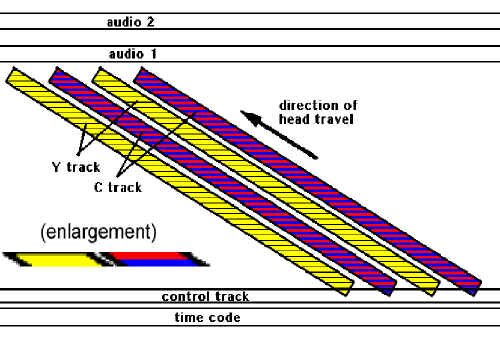
Betacam tracks (note separate luminance [Y] and chroma [C] tracks)
|
Since the R-Y and B-Y signals never share the same track at once, there is no chance of crosstalk between them. This process of alternating the two components is called "Component Time Division Multiplexing" (CTDM).
The M-II format is very similar to the Betacam format.
Digital Video Recording
Video recording gave broadcasters a valuable tool. As each new analog format appeared, signal processor and editor packages emerged to stabilize its electromechanical irregularities. Yet, an undesirable "multiple-generation syndrome" continued to surface. What is called noise is in reality a combination of phase modulation, transport jitter, amplifier noise, improper machine lineup, and a host of other small inconsistencies. Digital recording tries to solve these problems.
The physical reality of magnetic recording is ideally suited to digital concepts. Information is stored on tape according to the polarization of the magnetic particles in the oxide. In making an excellent saturated recording, all particles will be magnetized completely in either the "north" or "south" direction - exactly what we want for a digital recording (the "1"s and "0"s of the digital domain). In addition, error correction and concealment alleviate the effects of tape irregularities and events that leave momentary gaps in the recording; this is achieved using some elegant procedures. Analog recording places adjacent parts of images next to each other on the tape. The concept in digital recorders is to spread pieces of the image over a large area on the tape, so no adjacent pixels are written side by side.
Digital VTR Formats
Here's a listing of the digital video recording systems out there. This list changes all the time, making it almost impossible to keep up, especially in a publication of this kind, but it's reasonably current as of summer, 2003.
The D's: D1, D2, D3, D5, D6, D7, D9, D10, D11, D12
D1 was the first digital videotape format, and it is a component format. The digital video is not compressed. The video in/out can be RGB or Y/R-Y/B-Y, as well as Betacam component. This format is well suited to original non-NTSC work, such as graphics and film transfer. D-1 uses a 19mm metal-particle tape that is available in three different sizes of cassettes - the large one holds 96 minutes of program. It�s now obsolete.
D1 is based on the "4:2:2" component system described in CCIR Recommendation 601, which calls for a 13.5 MHz sample rate for luminance (858 samples/line) and 6.75 MHz for chroma. The "4:2:2" part is an representation of the sample rate: there are 4 samples of Y for every 2 samples of R-Y and 2 samples of B-Y. The samples are time multiplexed in the order B-Y, Y, R-Y, Y, and so on. We'll go into sampling in greater detail later, but for now, remember that 4:2:2 stuff, and the sample rate.
D2 is an NTSC composite format. This format is well suited as a "workhorse" in the broadcast environment, for handling program and commercial playbacks, as well as satellite recordings, since all of it is received by the station as NTSC video. D2 was designed to be a direct plug-in replacement for 1-inch and Betacam recorders, while D1 needs to work in a completely non-NTSC environment. D2 operates at the same 4x subcarrier (14.31818 MHz) sampling rate as most TBCs and frame syncs, and some existing equipment has been adapted to plug directly into the D2 machines.
D2, by the way, uses the same three cassette sizes as D1, but the tape lengths are different and the cassette can hold twice as much material as D1 - three hours for the large "D2L" cassette.
While all of this looks good as a theory, the fact of the matter is that D2 never really caught on, due to its initial upgrade cost, and that it was quickly supplanted by D3 and later digital recorders. It�s now obsolete.
D3 uses �" tape instead of the 19mm (3/4") tape used in D1 and D2. It also uses a different error correction system, a different modulation coding system (for recording), and a low-tension, low-friction transport. D3 is plug-in compatible with D2 - it's a composite format. In addition, D3 uses a flying erase head for insert editing - D2, in contrast, just records over previous material, which, in fact, works out because of the nature of digital recording. This machine is now obsolete.
D4 does not exist - it�s said that the Japanese consider the number 4 to be unlucky, so this digital VTR "version" never appeared.
D5 is D3 playback compatible, but offers 10-bit processing (which some say improves the quality of the recording), and is a composite and component VTR. This machine is now largely obsolete.
D6 is a digital HDTV recorder that records 64 minutes of 1.2 GBytes/sec video on a D1 large-shell cassette. Luminance sampling is 72 MHz and chroma sampling is 36 MHz. Sampling happens on an 8-bit level. Notice that this format specifies its recording ability not as "NTSC" or "HDTV" per se, but as a capability of recording so many "bits per second."
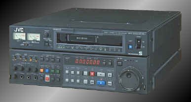
| D7 is the standard for Panasonic and DVCPRO, which is a 4:1:1 component machine with 8-bit recording and 5:1 compression using DCT (direct cosine transform). We will go into DCT later on, but for now, notice that this is the first "D" series machine to use compression. This format is also compatible with the many MiniDV camcorders out there. |
DVCPro
|
D9 is the proposed standard for Digital-S, the format from JVC that is to replace S-VHS. Digital-S uses full 4:2:2 sampling, with 8-bit recording and a 3.3:1 DCT compression scheme, in a �" tape in a shell that looks like an S-VHS cassette. The specification calls for four channels of audio, even though only two are used in current machines. Its video inputs accept composite, component, digital component, digital composite, and S-video. The machine will play back your existing S-VHS library.
D10: MPEG IMX. A digital component system, which will record and play back MPEG encoded video. It will also play back all Betacam formats (digital or analog) except for HDCAM, making it a possibly excellent replacement for existing "workhorse" VTR playback and record applications such as master control, satellite feedroom recordings and so on.
D11: See HDCAM, below.
D12: See DVCPRO 100, below.
Digital Videotape Recorders: The Others
Betacam SX (Sony) is a 4:2:2 component VTR with 8-bit resolution and MPEG-2 compression of 10:1, recording on �" metal particle tape with four channels of 16-bit audio. This VTR plays back everyone's vast library of Betacam SP tapes.
DCT 700d (Ampex) uses 2:1 compression on a proprietary tape format, 3/4" wide. It's an 8-bit format, taking composite, component, and digital component inputs and outputs. It�s now obsolete.
Digital Betacam (Sony) is a 4:2:2 component VTR with 10-bit resolution and a 2.34:1 compression ratio on a 1/2" metal particle tape. This VTR also plays back everyone's vast library of Betacam SP tapes.
DVCAM (Sony) is a 4:1:1 component system, 8-bits resolution, with 5:1 DCT intraframe compression. It's similar to D7 (DVCPRO) in many respects, but incompatible. It will play back Sony's consumer DV tapes, making it possible to record on inexpensive digital camcorders for "disposable camera" shooting by broadcasters.
DVCPRO 50 is a close cousin of DVCPro (see D7, above), but is a 4:2:2 component recording system, instead of 4:1:1. Its compression rate is a little less, too, at 3.3:1. It will take composite input as well as component.
D-VHS is the replacement for consumer VHS. It will have no analog inputs or outputs - the VCR will be fed from digital off air or digital cable or satellite dish signals, and its output will be sent directly to digital televisions (DTV.) It will be capable of recording any of the proposed DTV formats (of which we will study later in this text), and will play back your existing library of VHS videotape.
HDCAM (D11) is a format that uses �" metal particle tape (unlike D6, the other HDTV format, which uses 3/4" tape.) The idea behind this is to enable handheld HDTV recording, because of the smaller transport. There are some tricks to this, though: HDTV is set up as 1,920 pixels across - HDCAM reduces this to 1,440 (4:3 subsampling). This can be represented in the shorthand of the day as 3:1:1.
DVCPRO 100 (D12) is the HD version of regular DVCPro. A very new format so details were sketchy at time of publication of this textbook (summer, 2003).
How Digital VTRs Record and Play Back
The digital systems vary somewhat in their processes and track layouts on the videotape, but the principles are the same for them all.
In some systems, the video enters the recorder as digital information or component video; in others, the video is in composite form. If the video is in anything other than digital form, it is first converted to digital via A/D converters. Once the video is in digital form, it is "pre-coded," a kind of organized scrambling. This effectively breaks up the video into a pseudo-random pattern; originally adjacent pixels are no longer next to each other.
Similar procedures are performed on the four audio channels.
Because of all the shuffling and coding that's taken place, it's possible that a very low frequency signal has been created (one with not a lot of fast changes in the "0" and "1" pattern). This signal cannot be recorded to tape - you need fluctuations to make a recording. The solution has its direction in mathematical and physical theory that states that random noise has no very low frequency (DC) component. Therefore, the shuffled data stream is modulated (digitally, this time) with a pseudo-random sequence of "1"s and "0"s, called non-return-to-zero-transition-on-I (NRZI) code. More on this code later when we go into digital video in general, in that chapter.
In the D2 system, it's modulated with a pattern of "1"s and "0"s known as Miller-squared code. The intriguing thing about this particular pattern is that it is insensitive to amplitude variations and confines its signal energy into a relatively narrow bandwidth, compared with NRZ code. The D2 system has no guard bands between adjacent tracks written on the tape (there's an azimuth offset between the two recording heads, like some other helical scan formats). The restricted bandwidth of Miller-squared code reduces crosstalk between D2 video tracks, and also has another valuable characteristic in that it can overwrite its own previous recordings. This means a flying erase head is not required in D2.
D3 and D5 use something called 8-14 modulation coding, and use a flying erase head. But the principles and the point of it all is the same - don't have any low frequencies which we have to try to record on the videotape.
Recording On The Tape
Finally, it's time for the video (and audio tracks) to be recorded to tape.
D1
|
D1 track layout
|
The design of D1 is to capitalize on performance characteristics available with digital signals. D1 records the video information at both ends of the recorded track, with the audio information in the centre, to keep it away from the more damage prone edges of the tape. Audio data is written twice. When doing audio insert edits, one copy of the original audio data is retained, in case a different approach to the edit is preferred later on. There are additional longitudinal tracks - cue, control, and time-code. The rotating heads' azimuths are set at 0 degrees. There is a guard band between the tracks. |
D2
| D2 answers the need for a more economical format in applications where the digital output can be appreciated, but component or fully digital technology is not required. It records the video information in the centre of the recorded track, with the audio information recorded redundantly at each end of the track. There are the same group of longitudinal tracks as D1. The rotating heads' azimuths are set at +15 and -15 degrees for a total offset of 30 degrees; there is no guard band between adjacent tracks. |
D2 track layout
|
D3 and D5
D3 and D5 are similar. D3 records its audio on the ends of the tracks, and D5 records the audio in the middle of the tracks. The interesting thing about the D5 machines is that they can be configured to play back D3 recordings!
D6
|
D6 track layout (note clusters)
|
D6 is an HDTV recording format. But, since HDTV can take on many formats depending on country of origin, the basic structure of the D6 recording format is in fact that of a data recorder and not just that of a video recorder. Regardless of the source image, all recordings employ the same track pattern, error correction, and modulation code. The most interesting thing about D6 is that the information is recorded in "clusters" of 8 tracks each. The first and last sectors within a cluster contain audio data (redundantly recorded at the beginning and end of each track) while the middle sectors contain the video. Odd numbered tracks (1, 3, 5 and 7) have chrominance information while the even numbered tracks (0, 2, 4 and 6) have luminance information. Clearly, this is a component recorder. |
DVCPro
| DVCPRO is based on the consumer DV format (which was assembled by a consortium of more than ten manufacturers.) The PRO format, however, uses a wider helical track and a higher tape speed (33.8 mm/s vs. 18.8 mm/s). An interesting track arrangement has been designed into DVCPRO: an area called "ITI" (holding such information as time code) starts the track, followed by audio, then video, and then finally an ending segment called "subcode". Also, each frame of video is recorded as ten tracks, so there isn�t the "one track per field" arrangement as in other recorders. |
DVCPro track layout (note ITI and subcode segments)
|
Damage Control
Suppose that you lose 20 pieces out of a 1000 piece picture puzzle before it is assembled. The result is not total destruction - when the puzzle is assembled, the error is spread out. If you view the assembled picture, you can still see it, although you may need to interpolate some spots. That's the concept behind processing in the digital formats. In the digital recording and playback system, mapping transforms are used a lot. Not only is a field broken into segments and sectors, but also the segments, sectors and individual lines undergo shuffling. As a result, tape damage, instead of destroying portions of the picture, may appear as little faults spread over the picture.
Error Correction
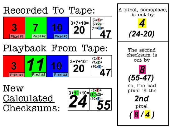 |
Here's an example of how error correction can work. Suppose you have the following values of three pixels: 3, 7, and 10. If you add the values together, you get 20. This total is called a checksum. You can make an additional checksum by "weighting" the values of the pixels and adding them up again. If we multiply pixel #1 by 1 we get 3; multiplying pixel #2 by 2 gives us 14; multiplying pixel #3 by 3 gives us 30. If we add these three new numbers up we get 3 + 14 + 30 = 47. This is our second checksum. Notice how the weighting factor is dependent upon the position of the pixel.
Suppose that now we read our three pixels off tape, and we get the erroneous values of 3, 11, and 10 (the second pixel is wrong). The addition of these values comes to 24; the addition of the weighted off-tape values (3, 22, 30) comes to 55.
Using our original checksums, and the off-tape incorrect checksums, we see that we're high by four (24-20) in our values some place, and it is in pixel number two (55-47 � 24-20). Sure enough, it's the "7" pixel that got read out as a "11". We can correct it, and replace it in the picture with the proper value.
The pixel is off by four in its actual value (24-20), and the actual pixel that's wrong is pixel number two [(55-47) � (24-20)].
|
Error Concealment
|
The other process used to suppress problems is error concealment, which is interpolation. In dropout compensation in an analog VTR, missing information is replaced from the previous line's video. In error concealment, values of a group of adjacent pixels are applied to a mathematical formula to determine the probable value of the missing pixel. These algorithms can be quite complex. If minute details involved many single, separated pixels of vastly different luminance and chrominance, and a pixel was missing somewhere in this complicated video detail, error concealment might not regenerate the lost data properly. Television, however, seldom has this type of detail, especially over a period of several TV fields.
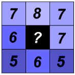
Imagine a group of nine adjacent pixels, with all of the values known except for the centre one:
The simplest interpolation of a situation like this is to just add up all the outer pixels and divide by 8:
7 + 8 + 7 + 6 + 7 + 5 + 6 + 5 = 51 � 8 = 6.375
The missing pixel has a value of about 6. This is a simple algorithm, but it illustrates the principle.
|
|
Track Size
|
|
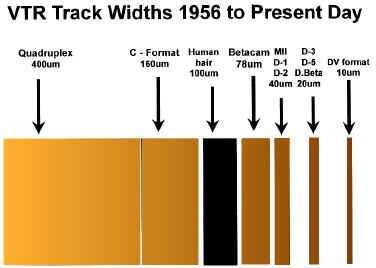
With the yearly advancement in digital and analog videotape recording, there has been a parallel reduction in the track width.
The moral of this story is simple: keep your videotapes and videotape machines scrupulously clean, and always store videotape in a protected environment, away from extremes of heat, cold, humidity, magnetism, and dust.
|
Digital Versatile Disk (DVD)
While engineers keep trying to perfect a broadcast quality re-writable optical disk, another format has come into being that is of the write-once-read-many (WORM) variety - DVD.
A later evolution of the compact disc (CD), the DVD has a storage capacity that is seven times higher than its older relation. The recording "pits" are less than half the diameter of a CD's, and the track can sometimes exceed eleven kilometres in length. All of this adds up to 4.7 gigabytes of storage - typically room for 135 minutes of widescreen (16:9) video at MPEG-2 quality accompanied by multiple audio and subtitle channels. This is called the DVD-5 format. Two-sided versions are available, too - a flippable format not seen since the days of vinyl LPs - the DVD-10. With this capability, along with multi-layer versions of the disk, storage capacity of up to 17 gigabytes is available - the DVD-18.
While not strictly a broadcast video recording format (it�s a write-once technology, remember) it has its uses as a more or less permanent storage medium where applications require many short duration elements for live or edited production, quick changes in live to air elements, or several versions of interstitial elements. In addition, this format is now readily accepted into the home due to its relatively low cost and high quality. We can expect to see DVD players in broadcast applications at consumer prices.
Things To Think About:
Videotape recording has been around for about 40 years. The key to its invention is the concept of the rotating head wheel, achieving high head to tape speed. But, we have to FM video so that it can be played back cleanly, and use servos to control the tape transport and head drum motors. Even with servos, we still need some kind of time base correction to completely stabilize the signal. The principles of analog video recording haven�t changed in decades, so it�s a good idea to be familiar with them.
There have been various analog formats created over the years, and some of them are still with us today. All formats still in use are helical wrap machines. There are ways of creating slow motion effects with these modern VTRs. How is this done?
Component VTRs are replacing composite recorders. They use ingenious means to keep the luminance and chrominance separate. Be familiar with the fundamentals of component recording.
Digital video recording is the new frontier. In only several years there have been several formats created and already some of those are obsolete. Be familiar with the current ones and know the principles of digital videotape recording including error correction and concealment.