|


|


"There was a time in this business when they had the eyes of the whole wide world. But that wasn't good enough for them. Oh, no. They had to have the ears of the world, too. So they opened their big mouths, and out came talk. Talk! Talk!!"
-- Gloria Swanson lamenting the demise of silent films in Sunset Boulevard
Principles of Sound
Audio frequencies are those perceptible by the human ear. All sound is produced by mechanical vibrations. When something vibrates, it alternately compresses and expands the air around it. These condensations and rarefactions are transmitted to adjacent air particles. Therefore, some of the energy of a vibrating surface is transmitted away from it and may affect our hearing mechanism, providing the vibrations are those we can hear.
|
Sound needs an elastic medium - solid, liquid, or gas - to go through; it cannot exist in a vacuum. When a region of a material is compressed, it exerts a tug on its neighbouring regions, and they in turn pull on their neighbours. If the area is expanded, it will push on its neighbours, and that push also will go through the medium. Alternating compressions and expansions create regions of alternating high and low density which move throughout the material; the result is a sound wave. As the wave goes by, each particle in the substance oscillates back and forth.
|
|
|
How we graphically represent compressions and rarefractions
|
The pitch of the sound is determined by its frequency - the rate at which the vibrations occur. The unit of frequency is called a Hertz (Hz); 1 Hz is equal to 1 vibration per second. An alternate term is "cycles per second." The human ear is sensitive to frequencies between about 20 Hz and 20,000 Hz. Frequencies lower than 20 Hz are called infrasonic; those higher than 20,000 Hz are called ultrasonic.
The magnitude of the changes in a material associated with a sound wave are remarkably small. For example, a tone of middle C (261 Hz) played in air as loudly as the ear can tolerate, results in density changes of less than one-tenth of a millimetre (0.004 inches).
|
|
The wavelength of sound is the distance between two adjacent compressions. For example, for a tone of middle C in air, the wavelength is about 1.2 metres (4 feet). The frequency, the wavelength, and the speed of sound have this relationship:
speed = frequency times wavelength
|
|
|
|
The shorter the wavelength, the higher the frequency (more cycles per second)
|
The most important, and technically the most impressive, of sound receivers is the ear - it can detect sound density changes of less than one ten-millionth of 1 percent. This figure corresponds to a particle displacement of less than .0000001 millimetres. Now that's small.
Because the range of acoustic amplitudes that the ear can detect is so large, a special compressed scale has been devised to describe acoustic intensities. In this "decibel" scale a 10-decibel (dB) difference between two sounds is perceived as a loudness difference of a factor of two. Regular exposure to sounds of about 90 dB will eventually cause hearing loss, and sounds of 130 dB can cause immediate and permanent hearing loss.
Sources of Sound - Microphones
A microphone is a device that transforms sound into electrical signals. The signals can then be transmitted, amplified, recorded electrically and, finally, converted back into sound.
All microphones contain a thin membrane - either a diaphragm or a ribbon. The membrane vibrates in response to the sound striking it. A transducer (the term is taken from the Latin "lead across") connected to it generates an electrical signal that is equivalent to the vibrations in frequency and amplitude.
Types of Operation
Microphones may be classed by operating principle. The main types are carbon, piezoelectric, dynamic and capacitor.
|
The carbon microphone used to be the basic part of a telephone transmitter - it is not normally used for broadcast. It consists of a cup containing loosely packed carbon granules next to a thin metal diaphragm. When sound waves strike the diaphragm, they cause a change in the electrical resistance of the carbon pack that is proportional to the change in pressure. As the carbon microphone doesn't actually generate any electricity of its own, an external battery is required. Also, the carbon particles have a tendency to pack over time, which requires an occasional tap to loosen them. Although we no longer use carbon microphones in this business, it's a tradition that continues to this day - tapping the microphone to see if it's working!
|
|
|
Carbon microphone
|
|
|
In the piezoelectric, or crystal, microphone, the diaphragm is linked to a transducer crystal (Rochelle salts or barium titanate are commonly used). The distortion of the crystal by the sound waves generates a small electrical signal.
|
|
Piezoelectric microphone
|
|
The dynamic microphone has the diaphragm attached to a coil of wire that moves within the magnetic field of a permanent magnet. The coil generates the signal voltage by electromagnetic induction. When wire is wound in a coil, electricity can be generated by moving a magnet within the coil. This is because the lines of magnetic force created by the magnet are powerful enough to jiggle electrons free within the wire when they cut across the magnetic field at right angles. The electricity is only generated while the magnet is moving. It's the change that does it. Therefore, in our microphone, the moving coil (attached to the diaphragm), makes small electrical currents that we can use.
|
|
|
Dynamic microphone
|
|
|
To explain the capacitor (or condenser or electrostatic) microphone, we must understand what a condenser is.
Take a parallel pair of electrodes, separated with air or some other non-conductor - this is a condenser. Apply an electric current to them. Electrons will rush from the more negative one to the more positive one, in an attempt to balance the electrical potential between them. If you take the current away, the plates will temporarily have a charge on them. You can now use that stored charge for other purposes. The word condenser was thought up by the first experimenters who thought that collecting electricity was "condensing" it. To make it more confusing, we now call condensers "capacitors."
|
|
Electrostatic (or condenser) microphone
|
Okay, then. The condenser microphone contains a thin metal diaphragm that is stretched close and parallel to a fixed metal electrode; this is our condenser. We then add a charge to this condenser. The sound waves generate vibrations in the one flexible diaphragm plate, which will cause a small change in the otherwise fixed voltage available to us. Since the diaphragm's vibration results in a variation of our condenser's ability to store a charge, we can amplify and use that change.
The electret condenser uses a permanently polarized capacitor, so you don't need a power supply to charge the plates. Electret microphones are still hooked up to a battery, however, because the signals they generate are so weak that it they have to be amplified before being sent down the microphone's connecting wires.
Loudspeakers
A speaker is a device that converts electrical energy into mechanical energy. This in turn, pushes air, producing a sound.
There are different ways to make a loudspeaker, but one particular type is the most popular because of its efficiency and wide-range response. It is known as a dynamic, or magnetic loudspeaker.
In the dynamic loudspeaker a permanent magnet (or electromagnet) produces a magnetic field. A coil of wire located within the magnetic field is energized by an electrical signal representing the sound to be reproduced. Since a variable magnetic field is generated in the coil, the coil is alternately attracted to and repelled from the magnet. The coil is glued to a cone of paper, which vibrates and causes the surrounding air to vibrate, re-creating the original sound. By the way, this is the reverse principle of the electromagnetic theory used in the dynamic microphone, discussed a few paragraphs back.
|
 |
|
Dynamic loudspeaker (courtesy How Stuff Works)
|
Sound Recording
Sound recording involves the electronic detection of sounds and their preservation in analog or digital coding in a storage medium - usually a disc, tape, or film. In reproduction, or playback, the encoded information is recovered from the storage medium, amplified, and fed to loudspeakers or headphones that re-create the original sound.
The Storage Medium
Sound recording technology can be classified into five storage media:
Mechanical Recording
This technology is the basis of all phonograph records. The audio signal is represented by an undulating groove in the surface of a cylinder or disc. For playback, the record spins on a turntable while a lightweight stylus traces the pattern of wiggles in the groove.
Magnetic Recording
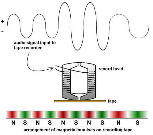
The basis of all tape recording (both audio and video), magnetic techniques are also used for the sound tracks of some 70-mm motion-picture films. In all cases, a plastic tape or film carries a thin coating of magnetic material, usually a metal oxide, on which a varying magnetic pattern is imposed during recording.
Optical Film
This technology is used for the sound tracks of all but a few motion-picture films. During recording a "light-valve" varies the amount of light passing through a lens system reaching the sensitized film - the strength of the light changes with the sound. In playback the developed film transmits a varying amount of light to a photocell, which creates a varying electrical signal.
Optical Disc
This is the basis of the compact disc (CD), digital video disc (DVD), and the optical videodisc. The signal is represented by a pattern of microscopic pits along a reflective spiral track in the disc. In playback, the pattern is "read" by a small laser and photocell.
Solid State
With the proliferation of flash memory media such as Compact Flash, Smart Disk, Memory Stick and other devices, we now must include this type of recording medium along with the other, more traditional, types.
The Form of Signal
Sound recordings are also classified according to the form of the signal that is stored:
Analog (Amplitude Modulation or AM)
All sound is characterized by a pattern of rapidly varying air pressure. In analog recording, that pattern is imposed directly upon the storage medium, as the undulating groove in a phonograph record, the varying magnetic pattern in an analog recorded tape, or the varying light pattern of a film sound track. The principal drawback of analog recording is that imperfections in the storage medium (for example, the particles of dust in a record groove or on a film sound track) can become part of the audio signal during playback.
Frequency Modulation (FM)
Used for recording the sound and picture in videodiscs and "HiFi" videocassettes, the sound-wave pattern is represented by slight variations in a recorded base frequency or carrier signal whose average frequency is above 1 megahertz (MHz). This approach requires more complex circuitry, but it avoids the limitations of direct analog recording.
Digital
The sound is represented by a binary (two-state) code in which the recorded signal alternates between "on" and "off." Of several possible coding schemes, the most commonly used is "pulse code modulation" (PCM). Error correction codes are included in the recording, allowing near-perfect re-creation of the original audio signal during playback.
These recording methods may be used to record audio or video. In principle, each of the forms (AM, FM, and digital) may be used with any of the four storage technologies, yielding up to twelve possible combinations. For example, mechanical-type disc sound storage with stylus playback has been used for analog recording (the familiar phonograph record); for FM recording (the CED videodisc system that was briefly marketed in the United States by RCA); and for digital recording (the Teldec Mini-Disk system, that was proposed as an alternative to the compact disc).
Popular Audio Recording Formats
For a description of phonograph records, cassettes, audio head configurations and tracks, CDs, and DAT (digital audio tape), please refer to the Appendix.
 |
Analog Recording and Playback on Magnetic Tape
In recent decades magnetic recording has become the most popular of all recording technologies, mainly because of the ease with which magnetic signals can be recorded, edited, copied, erased, or rerecorded. When an electric current flows in a coil of wire, it generates a magnetic field. Conversely, when a magnetic field moves near a wire, it generates an electric current in the wire. These physical phenomena are the basis of audio tape recording (conversion of an electrical signal to a magnetic pattern) and playback (conversion of the magnetic pattern back to an electrical signal).
A tape recorder consists of two systems: a tape transport mechanism that moves the tape past the heads at a uniform speed; and record and playback electronics that prepare the signal for recording and then amplify it in playback.
|
|
Magnetic recording and reproducing
|
The actual recording or playback is done by a "head," a small electromagnet mounted in a shielded case. For recording, the signal current generates a magnetic field in the head that is imposed on the magnetic particles in the tape. For playback, the magnetic fields in the moving tape generate tiny electric currents in the head. At each instant the head is in magnetic contact with a very small area of tape (in an audio cassette, that area is about 0.0001 inch wide by 0.02 inch high) containing several thousand particles. Some recorders have separate heads for recording and playback.
Each microscopic particle of iron oxide is an individual bar magnet oriented lengthwise on the tape, with a north pole and a south pole. In an unrecorded tape, about half of the particles are magnetized with their north pole forward, and the other half are oriented with their south pole leading. When exposed to a magnetic field strong enough to overcome their "coercivity" (resistance to change), the particles adopt the imposed field direction, reversing poles if necessary. Thus, the process of recording is simply one of flipping each particle's magnetic orientation one way or the other. Once set, the particles keep their magnetic orientation until exposed to another strong field. (For analog recording, the audio signal is combined with a strong "AC bias" signal that alternates from north to south and back around 100 KHz.) The result is that the audio waveform is faithfully represented by the percentage of north forward particles at each location along the recorded track.
To erase a recording, an "erase head" exposes the tape to a version of the bias signal, whose rapid polarity reversals leave half of the particles magnetized in each direction.
Audio Consoles
Let's now turn to the nerve centre of the entire operation - the console. It's here that signals flowing from mics, turntables, tape recorders and players are amplified, mixed, balanced and routed to air or tape.
At first glance, consoles may look threatening. They're really not - and they all operate on quite basic principles. They can be considered to have three basic systems: input, output and monitoring. As we go through a typical audio board, keep in mind three points: we have to get the signals from each sound source to inputs on the console; combine them; and monitor what we're doing.
We'll look at a single channel of the console, or "strip."
Input Selection
On most consoles, there is an ability to select from two different inputs on a given audio "strip". Unfortunately, you only get to choose one of these sources at a time to work with.
Level Setting
If it's a microphone you've chosen, its low level will have to be amplified to what we call "line level", so each strip contains a microphone preamplifier, which can be switched in and out of the line.
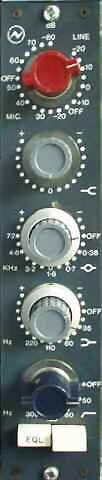
Equalizers
An equalizer is a device that alters a sound by boosting or reducing selected frequencies. We usually have one of these on every fader in our console (except for the submasters and masters). More on these later on in this chapter.
More Level Setting
We have managed to get all inputs up to what is called "line level," but we now need a way to vary the levels of the different sources. Enter the fader...or potentiometer...or pot...or attenuator...or gain control...or, if you insist, volume control. In principle, it's not much more sophisticated than a knob or sliding fader, like on your stereo system, except that it has calibrations on it.
Auxiliary Sends
These are rather like submasters, with two exceptions.
First, you can change the level going to the auxiliary output from each strip's source, regardless of the position of the fader for that strip. You also can decide whether to send the strip's source straight away, before you've used the fader to adjust its level, or after the fader. This selection is called "pre-fade" or "post-fade."
Second, auxiliaries don't normally go to air - they're used for operations like sending sources to control room or studio floor monitors, sending special material to the earpieces that on-camera talent are wearing, and sending information to telephone callers for phone-in shows.
|
 |
|
A typical audio console (featuring one strip)
|
Solo and Pre-Fade Listen
This type of button allows you to listen to a single channel off-line, sometimes through a special "cue" speaker and amplifier, and sometimes through the main monitor speakers, overriding any existing program material on those monitors.
On-Off or Mute
At times, we'll want to electrically separate the sound source from the board. So, we'll usually find a channel on-off key on each strip.
Professional audio operators do not use the strip's mute button to select sources while they are on air! All sources should be mixed using the main faders. This means that words and music will not accidentally be clipped by slow-moving operator's hands, or by unexpected cues. As well, in the heat of the moment, it is much easier to see if an audio strip is activated by looking at the larger faders on the board, instead of having to search for a tiny mute button, or a mute indicator light.
Phase Button
Normally, stereo audio signals are mixed together and laid down on audio tracks "in phase." Electronic transmission of sound is a series of voltage level waves. If a sound appears on two channels, and those channels are mixed , the sounds should "add up." If, for some reason, one channel is "out of phase" with respect to the other, the sounds cancel.
How could one channel ever get "out of phase" with the other in the first place? Consider that broadcast audio is a balanced system; two wires carry the signal, and a third is a ground connection. If somewhere in all the audio interconnections, those two signal wires are reversed in one of the channels, that signal will now be out of phase relative to the other channel. The obvious way to correct an electrical out of phase condition is to rewire the equipment properly. If there is no time for that, most consoles have a phase reversal switch that shifts one channel's phase by 180 degrees, back into phase.
Pan Pots
These allow us to shift the balance of sound to any point between the left and right channels of our stereo consoles.
Tying It All Together
We can make this "tying together" operation easy (but less flexible) or more difficult (but more versatile). If we bring all outputs to one final fader, that one becomes the "master" fader, controlling all of our sources to air. We also can group our sources together in "bunches," each bunch going to a separate "submaster" fader, which in turn, is bundled with the other submasters into the master. This submastering route allows us to vary sound elements in groups - for example, all the microphones, all of the VTR and line sources, "the band," or any other combination you'd like.
Keeping An Eye On Things
If our signals are too strong, they will overload equipment. If they are too weak, they will not overpower the background noise element in our electronics. We need an indicator.
There are many different types of audio level meters, but the most common one is the VU meter (VU stands for volume unit). The VU meter is an "averaging" meter in that it doesn't respond to sudden peaks in level - sort of like your ears. You can get VU meters in the standard, needle movement form, or as an LED or LCD display. They are calibrated in a scale that ranges typically from -20 VU to + 3 VU.
|
 |
 |
|
VU meter
|
PPM meter
|
|

|
Another meter commonly used in Europe (and increasingly, in North America) is the PPM (peak program meter). This device reads peaks in level rather than averages. The argument goes that although humans may not hear momentary peaks in loudness, the equipment does. Therefore, the PPM is better insurance against signal distortion. |
|
LED peak reading meter
|
When mixing audio, "ride the gain" so the level stays between -5 and 0 VU; ride a PPM meter at +8 dBm. It's normal for peaks and dips to go beyond this, of course. Mix with a light, fluid hand. Pots should not be jerked up and down to make adjustments at the slightest fall or rise in loudness. Changes should be smooth - you'll hear abrupt ones. Once again, this is another good reason to use the faders to activate channels, instead of the mute buttons.
Don't We Get To Hear It?
This part's easy. Take a tap off the master (or, using a selector switch, any of the submasters), and amplify it enough to drive loudspeakers. Perhaps put a level pot in the circuit so we can turn it down (or up!) when we want to. That should do the job. One precaution to be taken, however: many such circuits incorporate "mute" systems so when certain microphones' faders are actuated (or when an external mute switch is pressed), the audio at the speakers is automatically cut off. This prevents the dreaded feedback.
An Additional Extra - The Tone Oscillator
This is a signal generator that produces pure sine wave tones at selected frequencies. It is used to calibrate the console to connected tape recorders so their VU meters indicate the same levels, and to put reference tone levels on tape recordings.
|
|
A Bit More About Equalizers
Perhaps the most often used signal processor is the equalizer. Your home stereo system's bass and treble controls are primitive equalizers. There are three types in general use in broadcast - selectively variable (fixed frequency), continuously variable (parametric), and graphic. Their jobs are all the same: boost or cut the level of a selected frequency, or set of frequencies.
High Pass, Low Pass, Band Pass Filters
A high pass filter allows you to select a frequency below which signals will be removed, thus passing higher frequencies.
A low pass filter, as you might expect, allows you to select a frequency above which signals will be removed, thus passing lower frequencies.
It is disconcerting for newcomers to the audio operating scene to find that high pass filter controls have figures on them corresponding to low frequencies, and low pass filters having numbers relating to high frequencies!
A band pass filter allows you to select two frequencies - one below and one above which signals will be removed, thus leaving you with a band of frequencies that will be sent onwards.
Selectively Variable Equalizer
This unit is a series of band pass filters, and provides two or three ranges (or bands) of the frequency spectrum that you can vary. You can change where in each range (low, mid, high) you want to affect, and by how much boost or cut.
|
|
Selectively variable equalizer, featuring low cut, high pass, band pass, and low pass filters
|
Parametric Equalizer
This unit is similar to the selectively variable equalizer mentioned above, but you also can select how narrow (or wide) you want the band affected to be. This is known as affecting its "Q."
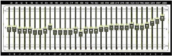
Graphic Equalizer
These are nifty looking units that allow you to "draw" on the front panel, by using a series of sliders, the frequency response you wish to achieve. The more sliders you have, the more delicately you can control your output - but the more expensive the unit becomes.
|
 |
|
Graphic equalizer
|
Things To Think About:
There's a relationship between the pitch of a sound, its frequency, and its wavelength.
Microphones and speakers work on similar, but opposite principles.
There are four common types of storage media currently used for sound recording, and three common forms of signal recording.
What are the basic principles behind analog and digital recording and reproducing?
Be familiar with some of the most common elements of a broadcast audio console.
Filtering is an integral part of radio and television signal processing. Acquaint yourself with the various filter types and their usage.