


 |


"Sattinger's Law: It works better if you plug it in."
-- Arthur Bloch, Murphy's Law and Other Reasons Why Things Go Wrong
Connectors, Patch Bays, Routing Switchers
In a typical television station, one is constantly surrounded by machinery with phosphorescent screens, small coloured indicator lights, knobs, levers, switches and pushbuttons.
To the uninitiated, just looking at a patch bay can send one into feelings of hopelessness. Or at the very least, eyestrain.
Some of the wires go from the machines to a patch rack, and some of those then go to another patch rack in another area. Others go to a patch rack, and then to a routing switcher, which is nothing more than an oversize, semi-automatic patch panel.
Some of the wires carry video, others audio, others time code (which is audio as well). Still others carry control signals from one device to the next.
In order to do work, we assemble the machines in some useable form using the interconnections. There are many correct ways to assemble the equipment - some are easier than others. There are also some incorrect ways to assemble the equipment. We will try to go through all of this.
Most of what you use in a "studio" environment is already connected together for us in a standardized fashion. But for flexibility, practically all of those standard connections go through patch bays so that custom configurations can be arranged and existing connections interrupted, at will.
Audio Connections
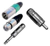
Broadcast audio requires three connections for each audio line. The audio signal travels down two of the three lines, with the last one tied to electrical ground. This is called a "balanced" line, and differs from most home audio equipment which sends the signal down a single wire AND the common "ground" or "shield" line. If you look at common broadcast connectors, you will see the three connections that have to be made, versus the two used in home equipment. Audio patch cords have all three wires in them.
|
 |
 |
|
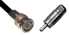
Broadcast (left) and consumer (right) audio connectors
|
XLR3 wiring |
 |
| Why we use balanced audio in the broadcast world |
Why do we do this? Often, audio signals must be run considerable distances (e.g., across studio floors, all around a TV station, etc.) And, usually running along with these audio cables are sources of high voltage and current, for example A.C. wiring. When two cables run side by side, larger currents from one cable (i.e., the A.C. power) induce small currents into the other cable (i.e., the audio line.) This is called electromagnetic induction, and is the basis for a device we call a transformer. But we digress.
Audio levels in a cable generally are around a fraction of one volt. Therefore, if even a little tiny bit of A.C. current is introduced into an audio cable, we'll have the dreaded hum, with which we're all too familiar. If you've ever tried to run a consumer audio cable twenty or thirty feet around a room, you'll understand the problem. But, all is not lost.
Suppose that we run two "versions" of the audio we're trying to send from one place to another. One of these is the "normal" one, involving a "signal" wire and a ground wire. We can send another version that uses a second "signal" wire and the same ground wire, but this version is 180 degrees out of phase with the first one. This means that it's electrically "upside down" from the first signal - when a voltage goes positive on the first signal, the voltage on the out of phase line goes negative by exactly the same amount. And vice versa. Think of the two signals as electrical mirror images of one another.
What's the advantage of this? If our equipment is designed so that we take both versions, invert the phase of the second signal so that it's back in phase with the first, and mix them together, what happens? For the signal part, not much - you get a little more level than before inside the equipment. But, if "hum" has been induced into both signals equally, it will travel to the equipment, one of the hums will be inverted in phase and mixed with the first one, and the hum part of the signal will be cancelled out!
 |
Video Connections
Broadcast video requires two connections for each video line. The signal travels down a single wire with the "shield" or ground as a reference and return path. If you look at common broadcast video connectors, you will see the two connections that have to be made.
|
|
Broadcast (left) and consumer (right) video connectors
|
|
|
Making The Connections
It would be an awkward situation if every time you wanted to use a piece of equipment, you had to crawl around behind the machine and plug in wires to connect it to the system. So, patch racks were a logical step. In any typical technical area you will probably find both audio and video patch racks. These traditionally connect the nearby equipment to one central area for further connections. Frequently, the patch racks are configured in such a way that if there are no patch cords in the system, equipment is ordinarily connected ("normalled") to other equipment. A common convention followed is "out to in," meaning that equipment's outputs are on the top row of a double jackfield, and equipment's inputs are on the bottom row. This makes normalling a straightforward and logical process.
|
 |
| Broadcast-type video patch bay and patch cord |
 |
| Broadcast-type audio patch bay |
Trunk Lines
If all the equipment were in one central area, there would be no need for trunk lines. The equipment would come to one large patch bay and would be interconnected there. But most facilities have equipment in several different areas in the building. Trunk lines are the next logical step. They are nothing more than a series of audio or video cables connecting one area to another. They are unbuffered, or amplified in any way. They're just wires.
Distribution Systems
Frequently, one is required to send a single feed to two or more different places. At first glance, it seems a simple matter to gather together the source machine's output cable, along with all of the destinations, and sort of "twist all the wires together" into a big connection, and that should do it. But electronics and physics being what they are, you don't get something for nothing. Because of the way broadcast systems are constructed, every time you add another wire to this primitive distribution system, you reduce the signal available to all the destinations. You've created a series of parallel connections. There is a solution to this, and it is used throughout the station.
|
 |
|
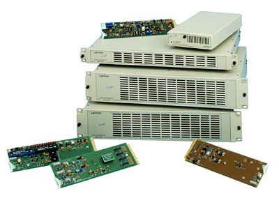
Various audio and video distribution amplifier racks and cards (courtesy: Leitch)
|
 |
Distribution Amplifiers
These units take a single input and pass it through four or six individual amplifiers, thus providing us with separate, isolated outputs. Those outputs don't load each other down. Whenever a signal is distributed to more than one place, a distribution amplifier (or "D.A.," for short) is used. There are different units available for audio and video. Some audio distribution amplifiers are "stereo," which simply means that there are two monaural units in one package. So, if you're sending a source to more than one place, use the spare D.A.s available at your patch racks.
|
|
Schematic diagram of a distribution amplifier
|
Audio Phasing
A mono signal from stereo channels is generally produced by summing the left and right together. When left and right signals are mixed together through a mixer, they will hopefully add together. In fact, the output should be approximately +3 dB (on your VU meter) more than each individual input. Sometimes however, the output signal seems to be very low level, frequently sibilant, and almost completely disappears. Why is this?
Normally, the signals are what is referred to as "in phase." Sound is a series of pressure waves, and electronic transmission of sound is a series of voltage level waves representing the sound pressure changes. If a sound appears on both channels, and those channels are summed together, the sounds should "add up." If for some reason, one channel is "out of phase" from the other, the sounds cancel out.
|
|
|
The results of mixing of "in phase" and " 180� out of phase" audio channels
|
 |
How can one channel ever get "out of phase" with the other in the first place? Consider the fact that broadcast audio is a balanced system; two wires carry the signal, and a third is a ground connection. If somewhere in all the audio interconnections, those two signal wires are reversed in one of the channels, that signal will now be out of phase with the other channel.
How can this be remedied during further production and dubbing? A special patch cord, generally referred to as a "phase reversal cable" has those two wires switched over within its connections. Therefore, with this cable, an out of phase channel can be put back in phase with respect to its accompanying channel. Or if it is already in phase and the phase reversal cable is used accidentally, the channel will be put out of phase, causing future problems! A very useful cable, but a potentially dangerous one as well.
|
|
A schematic of the difference between "normal" and "phase reversal" patch cords
|
Routing Switchers
As mentioned before, routing switchers are large, automated patch bays. As the output from each device enters the routing switcher, it is put through many distribution amplifiers - one for each place to where it can possibly be switched by the system. The internal switches in the router are controlled by circuits which, in turn, are connected to routing switcher control panels throughout the building. When you select a destination, and a source that you'd like put there, the signal is switched in central racks - it doesn't go through the routing panel at all.
|
|
 |
|
A simple routing switcher
|
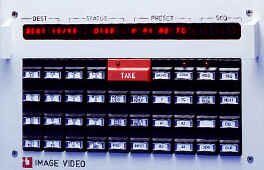
Routing switcher panel (courtesy Image Video)
|
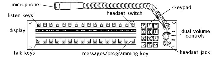
Intercom Systems
Connecting the humans all together is just as important as connecting all of the equipment together. The generally accepted way to speak to other parties involved in a television operation (apart from frantic screaming during an intense moment in the control room) is through an intercom panel.
Intercom systems come in various sizes, shapes, and complexities but the basic principle is the same in all of them: transmit someone's voice to some other particular person, with no distortion or interruption from other parties. Sometimes many parties may need to speak to one individual; often that one person wants to speak with a whole group of people at once.
|
|
|
RTS-Telex intercom panel (click on the picture for a bigger view)
|
 |
The standard intercom system will involve several intercom base stations (the ones mounted in control room consoles and equipment areas); floor director belt packs; camera headsets; on-air talent IFB (interruptible foldback earpiece); a source of on-air program audio that's normally being fed to the on-air talent; and, with modern systems, some type of computerized control over the whole system. In addition, more complex systems may involve the ability to interface with someone on a telephone outside of the production facility; incoming satellite communications from a remote feed; wireless talent IFB and wireless floor director systems; and interconnection with two-way hand held radios. |
|
Typical intercom system, showing the various devices that can be connected
|
Data Circuits
Beyond the usual video and audio connections, there are many other control signals being sent around the station. Some control character generators and switchers; others start and stop videotape machines by remote control; still others steer satellite dishes. Whole books could be written about these signals; in fact, they have been - see the bibliography.
The easiest way to think about all of this "data transmission" is to break it down into three parts: a transmitter of information, the information path itself, and a receiver of the data. Often, the same piece of gear will transmit and receive signals. These systems don't use human language; they have their own specific series of codes to tell each piece of equipment what to do.
Terminals
Terminals are the human interface to the machinery. Some people think of terminals as CRT screens with typewriter-like keyboards attached. Those are very common and are used extensively in a television complex within the computerized Traffic department and for some equipment monitoring functions within areas like the central engineering racks. But terminals can be found in almost any configuration.
A videotape editing remote controller is a terminal; so is the keyboard and CRT arrangement used with the character generator. The transmitter controls and alarm panels in a Master Control Room make up a kind of terminal, but instead of a CRT, it sometimes uses a series of lights to indicate the status of the transmitter. Some terminals can even be called up on the telephone and will speak to you; by punching in a series of numbers using a touch-tone phone, you can communicate with it, ask it questions about the status of equipment, get verbal responses, and even effect changes in the system. The routing switcher controllers and production switcher panels are terminals, as are the intercom stations. All of these terminals send commands to other pieces of equipment.
Talking To Machines
There are basically two ways of sending those commands. When using computers, we must communicate with them using only electrical signals - changes in the current or voltage on a wire.
Because computers are designed to sense the absence or presence of a voltage within an electrical system, the binary system is used. The "0" and the "1" are the symbols of the binary system; with computers the "0" represents an absence of a signal and the "1" represents a presence of a voltage. A binary digit is commonly referred to as a bit.
In the numbering system we humans use (base ten), we have the digits zero through nine to work with. In a number such as 345.27, we understand it to mean "three hundreds, plus four tens, plus five ones, plus two tenths, plus seven hundredths." Similarly, in the binary system, the columnar position of the numbers denotes their "weight" within the final number. Each additional column within the binary system is worth two times what the previous column was.
Counting up to eleven in the decimal system, involves:
Counting up to eleven in the binary system, where we only have two symbols, involves:
Congratulations. You can now count like a computer.
What can be done with these binary numbers? We can certainly do arithmetic with them, and all we need is an absence or presence of a voltage.
 It's also a very straightforward process to convert the letters of the alphabet and other special symbols into codes that can be represented by numbers. If we take the binary numbering system, and use eight columns (bits), we have a possible 256 combinations (28) to choose from. This is more than enough to represent letters, numbers, and special symbols. In fact, a system called ASCII uses 8 bits to represent these elements, and is used in virtually all computers in most of the world. These are the codes sent to and from monitoring terminals connected to some equipment. Click on the picture to the left to see a diagram of the ASCII codes.
Transmission
Now that we know how to count and talk like a computer, we need some way of getting our conversations across to the machines. There are two ways of doing this.
| In parallel transmission, each bit of a character travels on its own wire. An additional wire, carrying what is called a strobe, indicates to the receiver when all of the bits are present on their respective wires so that the values can be read. So, to send eight bits plus a strobe, and some form of common return for all of this requires at least ten wires. This is fine for short distances, but because of the cost of all that wire, it becomes prohibitively expensive over many feet or miles. |
 |
| Parallel transmission needs ten wires |
 |
Serial transmission is used for those purposes. Each bit is sent one by one down a single wire. Before the beginning of each "byte" (eight bits representing our character), a "start" bit is sent; at the end of each byte, a "stop" bit is then transmitted. This tells the receiving equipment where the beginning and end of each byte is located, relative to the continuous stream of "on/off" information. |
|
Serial transmission needs only two wires for one-way communication
|
Modems
Modems are simply a way of sending the serial chain of on/off sequences down a telephone line that normally expects audio frequencies. The modem is a unit that converts the on/off series into tones that differ depending on whether they're representing the "1"s, or the "0"s. This is a "modulating / demodulating" process, of which "modem" is the abbreviation. More expensive and complicated modems allow transmission of computer data at very high speeds, using various frequency and phase shifting methods.
Fibre Optics
Instead of using wires, it's possible to use the on/off electrical sequences to turn a light or a laser beam on and off. The resulting modulated light beam can be sent down a very small tube of glass fibre along great distances. At the other end, the flashing light beam can once again be converted into electrical on/off sequences. This is the principle behind fibre optics. The light doesn't come out of the sides of the fibre, due to the principle of refraction. With a fibre optic cable, there is a centre core of glass fibre with a refraction index that is slightly more than a coating (or cladding) surrounding the fibre. When a light ray enters the glass fibre, it may not be coming in exactly parallel to the edges. It will approach the cladding next to the fibre, but, because the cladding index is slightly less than the glass, it gets reflected back into the glass again, and so on, down the length of the fibre.
 Try This At Home!
When you look through a glass of water at an object, it doesn't appear to be exactly where it ought to be. This is because the light rays have been bent as they go through the water; the speed of the light rays increases as they leave the water. The water has a refraction index that is different from the air. This "total internal reflection" property can be illustrated with your glass of water: simply look inside the top of the glass, and you will see your reflection on the far side of the tumbler.
Interface Standards
All of the equipment around a television facility that uses these sorts of connections frequently have different types of connectors and different ways of talking to one another; terms like RS-232C and RS-422 abound.
RS-232C is a serial interface standard, and is commonly used for connecting computers to modems, video display terminals, and serial printers, usually employing a 9 or 25 pin connector. It uses large voltage swings (typically +/- 12 volts, but may be as high as +/-25 volts) to send the serial data. Also, all of the signals are referenced to a single common return (ground). This is fine most of the time, but sometimes runs into problems when equipment at either end of the transmission is plugged into an electrical outlet at different ground potential.
RS-422 attempts to overcome that problem by using separate wires for each signal; this is called balanced transmission. Because of the balancing, this interface can also use much lower voltage swings to represent the data - typically well within +/- 5 volts.
Things To Think About:
Broadcast audio differs substantially from consumer audio, and there are advantages and disadvantages to this.
Consider the ways in which equipment is connected together and distributed in a television station.
Modern intercom systems are very sophisticated. Be familiar with the people and locations which can be interconnected to communicate with one another.
Terminals are everywhere. Look around the television facility and note the various kinds of terminals.
Parallel and serial computer transmission differ, and there are advantages and disadvantages to each.