Home
Preface to Version 5.0
What's in a TV Station?
Brief History and Overview
Electricity 101
How It Connects Together
Audio
Analog Video
Waveform Mons & Vectorscopes
Monitors and TV Sets
Cameras
Lighting
Switching and Video Effects
Video Recording
Editing for TV
Film for TV
Digital Video
Transmission
The Near Future of TV
Appendices
Bibliography


"I introduced into my ears two metal rods with rounded ends and joined them to the terminals of the apparatus. At the moment the circuit was completed, I received a shock in the head and heard a crackling and boiling noise. This disagreeable sensation, which I feared might be dangerous, has deterred me so that I have not repeated this experiment."

-- Alessandro Volta

Without an understanding of how basic electrical circuits work, it's difficult to see how our television system fits together. So, this chapter will introduce some of these fundamental concepts.

An electric circuit is a series of electrical components connected together, forming a path for an electric current. The purpose of most circuits is to convert the electricity into a different form of energy such as light, heat, or sound. All electric circuits have four main parts:

a source of electric energy like: a chemical battery, generator, or solar cell
a load, or output device like: a lamp, motor, or loudspeaker
conductors like: copper or aluminum wire, to transport the electrical energy from the source to the load
a control device like: a relay, switch, or thermostat, to control the flow of energy to the load.

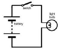
The source may be either DC (direct current, which does not vary in value) or AC (alternating current, which periodically reverses its polarity).

Series Circuits

A series circuit is one in which the current has only one path to take - from one side of the source, through the load, and back to the other side of the source. In a circuit with metallic conductors, this current consists of the drift of electrons moving from the negative side of the source toward the positive side of the source. Notice that a series circuit has two wires from the source to the load - one to send the electrons to the load, and the other, a return path, to return them to the source.

A flashlight is an example of a series circuit and is a simple DC circuit. To represent such a circuit, a pictorial diagram may be used. A method that is preferred by electricians and technicians is to use a schematic diagram with interconnected symbols, with each symbol representing an electrical component.

A simple series circuit

What�s inside a flashlight

The source in a flashlight is two series-connected dry cells, each having about 1.5 volts, to supply 3 volts to the circuit. A 3 volt bulb is the load, and a slide switch is connected between the source and load. The conducting path here is supplied by a metallic strip along the inside of the tube holding the batteries. When the switch is open, no current flows and the lamp is off. When the switch is closed, a complete path exists and current flows through the circuit, lighting the lamp. The current heats the filament of the lamp, and it emits light as well as heat.

Another common example of a series circuit is the series string of Christmas tree lights (some types of small, "twinkle" lights). The disadvantage of such an arrangement is that if one lamp burns out, the electrical path is broken and all the other lights go out. A recent development is a lamp that, once burnt out, becomes a short circuit; it offers zero resistance to a current. The dead lamp acts like a piece of wire and the rest of the lamps remain lighted. All the remaining lamps, however, will now have a little more voltage across them, and more current will flow in the whole circuit. The total power consumed in such a circuit is the sum of the individual powers used in each lamp.
Schematic of series Christmas lights

Parallel Circuits

A parallel circuit is one in which all the loads work at the same voltage as the source and independently of one another. If one load is switched off, the rest are unaffected.

The electrical system in an automobile is an example of a DC parallel circuit in which the 12 volts from the battery simultaneously supplies electrical energy for the ignition system, headlights, taillights, and radio.

If another load is added in a parallel system, it supplies another path for the current, so the total current needed from the source increases. The combined resistance of the parallel circuit effectively decreases whenever another load (resistance) is added in parallel. As in a series circuit, in a parallel circuit the total power is the sum of the individual powers required.

Why Are You Being Told All Of This?

Because...practically everything in a television station runs on electricity. Virtually everything in the technical side of television is a circuit.

The concept of a circuit "path" is one that should be kept in mind when dealing with all the station's functions. Remember:

Automobile electrical system (your vehicle, hopefully, is not quite as simple as illustrated!)

All equipment needs a "signal path" through which it gets video and/or audio, sends it on its way again, and gets control information from other devices and remote panels.

All television transmission is an extension of this signal path concept. We send it, it gets received. We can even see that it's receivable using our own off-air monitors.

All AC wiring in the facility is a network of series and parallel circuits. If you plug a light into the wall, you've created the simplest of series circuits. If you plug two lamps into the same duplex wall outlet, you've created a parallel circuit - made up of two series circuits, of course.

Things To Think About:

Most circuits convert electricity into another form of energy.

They have four main components. What are they?

There are series and parallel circuits. Can you compare and contrast the two types?

Why is this information important to us as TV people?