"You know, television was actually invented in the 1890s, but they couldn't get it to work until the '40s when they came out with gaffer tape."
-- Walter Pyle, CBS
Switchers
Up to this point, we have discussed some of the various individual sources available to us as production elements. TV production involves more than one of these sources, and so a method is needed to shift from one video source to another, or "join" them together. This device is a switcher, and is the video equivalent of the audio console.
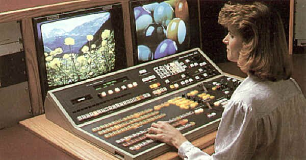
Grass Valley Model 200-1 video switcher (courtesy GVG-Tektronix)
Switchers can be simple or extremely complex in their production function and electronic design. All switchers, however, perform the same basic functions: selection of the proper video source from several inputs, basic transitions between two or more sources, and the creation of or access to special effects. Some switchers, called audio-follow switchers, also take the program audio associated with a video source; these are used in master control situations and will be discussed later.
Cutting
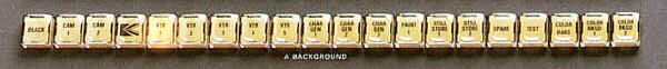
Switcher Program bus (courtesy GVG-Tektronix)
Switchers have rows of buttons called buses - each video input on a switcher has its corresponding button. Cutting from one source to another involves simply pressing the button assigned to the source. If all you wanted to do is cut from one source to another, a single bus would do. We usually require more sophisticated effects, so a slightly more complex switcher is required.
Dissolving
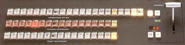
Two program buses, and key bus, with Program transition M/E (courtesy GVG-Tektronix)
To create a dissolve, we need to get at two different sources at once; this will require two buses, and some sort of way to go between them. We can use a slider, like that found on an audio console (and, in fact, some switchers do use such a slider), but a fader bar is the conventional way of controlling the fading rate.
To dissolve, we select the two different sources on the two buses, and push or pull the lever to move it to the other bus. When the lever is in the middle position, the output is in a "partial dissolve" or "super." We can still do our cuts with our two bus system, by pushing another button on the bus that is live to air.
Something to note: the video sources themselves do not actually go through the switcher panel that the operator uses. Instead, the panel is a sort of "remote control," that directs the actual switching electronics at central racks. For example, cutting from one source to another involves switching over only during the vertical interval of the video signals, so there is no perceptible "jump" in the picture when cutting.
How switchers do dissolves
Dissolving involves sending control voltages from the switcher panel (that vary depending on the position of the dissolve lever) to the main unit. Two "voltage controlled amplifiers" change their output level up or down to correspond to the control voltages. This creates the dissolve, which is really one source increasing in level while the other source is decreasing. This is like a "cross-fade" in audio.
Wipes
Wipes are a more sophisticated transition, when one television picture is removed with a relatively hard edge and another is revealed. They can be done using the same two buses. To add this new feature, we put on our control panel two buttons labelled WIPE and MIX so our fader bar can do double duty. Our bus pair is now called a mix/effect unit, or M/E.
How switchers do wipes
To understand how wipes are done in a switcher, consider a simple one - a wipe from the top of the screen to the bottom (a horizontal wipe). When the fader bar is at the topmost position, the entire screen is taken up with the top bus' source. As the bar is moved down, the switcher detects the voltage changes sent to it. Based on the new levels, it decides at some point during the field of video being displayed, to cut instantly over to the second source. So, the voltage level is used for positional information on the screen. This cut point is the edge of the wipe transition. As the fader bar moves more, this cutover point moves farther down the screen. Eventually, when the bar is at the bottom of its travel, the entire picture has been replaced by the second source.
A simple vertical wipe is like the horizontal one, except this time the voltages are interpreted as positional information for a switchover point along each horizontal line. The greater the fader bar moves, the more the second source is revealed.
Patterns
| Combining the actions of vertical and horizontal wipes gives you the ability to do corner wipes - those involving both left-to-right and top-to-bottom motions at once. These wipes - and usually many more variations - can be individually selected by a matrix of buttons on the switcher called the pattern selectors. Each button usually has a small picture on it representing the type of wipe that's selected. |
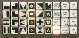
Switcher wipe patterns (Grass Valley Model 200) (courtesy GVG-Tektronix)
|
Soft-Edged Wipes
|
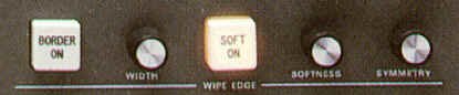
Wipe edge modifiers (courtesy GVG-Tektronix)
|
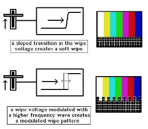
The wipe transition doesn't always have to be a hard edged one. Consider that in a dissolve, no voltage present from the fader bar means only the first picture will be present, and full voltage means that only the second video source will be shown. In a wipe, the voltage is converted to a position on the screen. The ramped effect of a dissolve can be combined with the positional information used in wipes to create a wipe edge that quickly dissolves from the first image to the second. This results in a soft edged wipe. |
Modulated Wipes
|
Soft and modulated wipes
|
The wipe doesn't always have to have a straight edge, either. You can further influence the wipe pattern by introducing to it an additional signal from an audio source, such as a tone generator. This creates modulated wipes with soft, curving lines (a sine wave generator), "teeth"-like lines (a triangle or sawtooth wave generator), or squared-off lines (a square wave generator).
Some switchers also allow you to modulate the wipe with standard, complex sounds from the output of an audio console, creating a wipe that oscillates in synchronization with the sound.
|
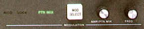
Wipe edge modulation modifiers (courtesy GVG-Tektronix)
|
Wipe Direction
|
There's no rule that the top of the fader always represents the top of the video picture, or the left of the picture. Sometimes you'll want to do a wipe in the reverse direction. To do this, additional direction buttons are made available, usually labelled with N (Normal), and R (Reverse). This just reverses the polarity of the voltages sent out from the fader bar.
A third button is sometimes fitted labelled FLIP FLOP or N/R (Normal/Reverse) which sets up the switcher to change automatically between Normal and Reverse modes with every wipe transition. Also, many switchers have a joystick positioner, which allows you to vary on screen the starting and ending positions of the various wipes.
|
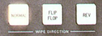
Wipe direction buttons (courtesy GVG-Tektronix)
|
Auto Transition Buttons
|
Auto transition module (courtesy GVG-Tektronix)
|
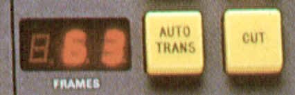
Nobody said we had to do all transitions with the fader bar. Most new switchers come with two additional buttons: AUTO TRANS and CUT. The AUTO TRANS allows us to do smooth dissolves or wipes to a predetermined timeline (usually measured in video frames' duration). The CUT button causes the source on the preset bus to cut to air. Often, as the new source is taken to air, the other is automatically positioned on the preview or preset bus, thereby showing up on the preview monitor. It's then ready to be taken to air at the next press of the CUT or AUTO TRANS button. This sort of transition type makes a two or three camera interview cutting situation very easy, with minimum hand reach over the live buses. |
Split Screens
|
If you stop a wipe half-way through its transition, it becomes a "split screen." On more sophisticated switchers, a PRESET PATTERN or SPLIT SCREEN button is available that allows you to vary the size of various wipes using an auxiliary set of controls instead of the fader bar. These controls, when used with the joystick, allow you to set up commonly used stationary boxes, circles, angles, corners and other effects without tying up a fader bar in mid-position.
Sometimes, with the use of a SYMMETRY control, the aspect ratio of certain split screen wipes can be changed. For example, a circle wipe also can be used as an ellipse, or a square box wipe can be elongated horizontally or vertically.
|
Mix/effects controls (Grass Valley Model 200) (courtesy GVG-Tektronix)
|
Keys - Internal, External, Matte
|
How switchers do keys
|
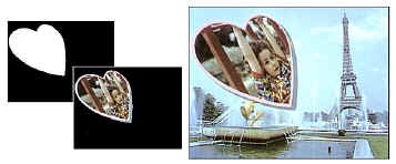
Keying refers to electronically cutting out portions of a picture and filling them in with another image. The basic purpose of a key is to add titles to a background picture, or to cut another picture into the background.
The cutting process is electronically similar to that used for wipes and split screens. However, instead of an internally generated control voltage, information from an external video source determines when to "cut over" from one source to another.
As video pictures do not usually contain extremely hard edges, an extra process is used to create the hard edge used as the transition marker. The video that will be used as the "hole cutter" goes through a processor that compares its luminance level at any particular moment with a reference voltage. If the luminance in the video signal is lower than the reference, the background picture remains on the switcher output. If the luminance in the keying video is greater than the reference, the second picture will be allowed to cover the background picture.
|
| This reference voltage can be varied using controls labelled KEY GAIN and CLIP. The Key Gain allows more or less of the keyed video to show through onto the background image depending on the luminance value at any one point in the keying video. The Key Clip control adjusts the �hardness� of the keyed edge between the two sources. |
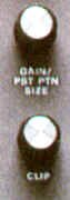
Gain and clip controls (courtesy GVG-Tektronix)
|
|
External keys and matte keys
|
There are various types of keys. If the cutout portion of the base picture is filled with the signal that is doing the cutting, it is called an internal key, normal key, self key, or luminance key.
If the cutout portion is filled by an external source, it is an external key. Sometimes the hole is filled with an electronically generated colour from the switcher; this is a matte key.
|
|

Key types (courtesy GVG-Tektronix)
|
Key Invert
|
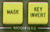
Key modifier buttons (courtesy GVG-Tektronix)
|
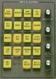
Normally, the keying action of a switcher is such that the lightest parts of the keying video create the hole to be filled. If the reverse situation is desired, most switchers come with an INVERSE button, which reverses the polarity of the key. For example, with a normal white graphic keyed over a background, the white graphic appears over the background video - the black graphic background is eliminated. Depressing the INVERSE button provides a "see through the graphic" effect - that is, a piece of the previous background scene in the shape of the white graphic letters is keyed over the graphic's black background. |
Normal and inverted key types
|
Mask Generator
| Sometimes, keying video has noise or other artifacts around the edges, marring the visual effect desired. Some switchers have an independent mask pattern generator that limits the display area of the keying signal. The boundaries of this pattern generator are often in the shape of a simple rectangle, and are manipulated by four rotary controls that vary the size, shape and position of the masked area. |
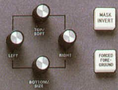
Key mask controls (courtesy GVG-Tektronix)
|
Chroma Key
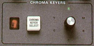
Chroma key hue and selection controls (courtesy GVG-Tektronix)
|
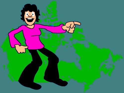
Chroma key is a special effect that uses colour for keying, instead of luminance. A control on the switcher selects which colour will become transparent during the keying process, thus allowing the background video to show through.
Usually green is selected if human performers will be in the shot. Historically blue was used if human performers were going to be in the shot, since it was most opposite in chroma phase to skin colour. The proliferation of blue jeans in the 1960s, and the fact that occasionally blue-eyed talent would have their eyes disappear gave way to using a bright green as the most common hue. Chromakey can, however, be used with any colour you wish.
Chroma keys come in two forms: RGB and encoded. In RGB chroma keys, the separate red, green and blue channels from a source (often a camera, although other sources with these outputs can be used) are brought into the switcher directly. From these separate channels the colour to be keyed out is selected. This has the advantage of cleaner keys since, to select a particular colour for keying, only a fairly straightforward mix of the three signals is required. Also, the video signal is not yet encoded and no NTSC-related artifacts have had the opportunity to blur the picture (and therefore the edges) that will eventually be keyed out. Finally, the chroma resolution has not been reduced by NTSC encoding.
Encoded chroma keys work in a similar way, but the quality of the key is usually not as satisfactory. The colour selection process picks a particular phase of subcarrier to eliminate, and since video pictures seldom have pure phase colours in them, the results are sometimes less than perfect. Additionally, the chroma resolution has also been reduced by NTSC encoding.
|

background
|
foreground (camera)
|
chromakey composite
|
Borders and Outlines
| Internal, external, matte and chroma keys can all have electronically generated drop-shadows and edges added to the keyed image. The key can also be shown as an outline key, which means that only the outline generated by the edge comparator will be shown; both inside and outside the outline, the background picture will remain. |
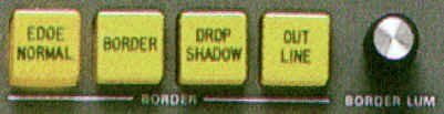
Border modifiers (courtesy GVG-Tektronix)
|
Downstream Keyer
|
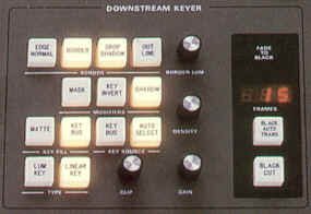
Downstream key module (Grass Valley Model 200) (courtesy GVG-Tektronix)
|
Downstream keys are the same as standard keying processes, except that they are generated by a separate keying module that is "downstream" (electronically) from the rest of the image-creating modules of the switcher. They can be used as a final keying point just before the video leaves the switcher. Downstream key sections of switchers often come equipped with a master fade-to-black bar, slider or auto transition button, to allow final fading of all effects without having to tie up an M/E bus to perform this conclusion. |
Other Standard Sources
In addition to the sources that we plug into a switcher, there are often other, pre-entered signals.
Often the left-most position on a switcher's buses will be black - a synchronous "no-video" source. It is used all the time for fade ups, break points, and a position in which the switcher should be left when not in use to prevent video images "burning in" on monitors.
Additionally, there will be a source of colour bars for videotape and monitor line-up, and as a test signal when making recordings, or sending the switcher output to another location.
| A background generator is often available to produce a full-field coloured background of any hue, saturation and luminance desired. Some more sophisticated generators allow gradual shading to black or another colour, or constantly changing (modulated) colour across the screen. Sometimes the background generator will serve double duty as the matte generator for matte keys within the keying module. More often, there will be at least one other separate matte generator reserved for the sole purpose of building these effects. Other places for separate matte generators include border colours on keys, and wipe edges. |
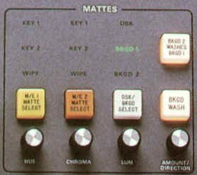
Matte generator module (Grass Valley Model 200) (courtesy GVG-Tektronix)
|
Re-entry and Cascading
So far, we've described a simple switcher with one M/E bus that can do (one at a time) a dissolve, a wipe or a key. It is possible to make a switcher with more than one M/E bus, and have each bus feed succeeding ones. This arrangement is often compared to a series of small waterfalls each trickling into the next and so this type of switcher is called a cascading switcher. It is also called a re-entry switcher, since the output of each M/E is "re-entered" into the input of the next, so effects can be layered on top of one another.
Other Buses
Other useful buses are often found on a switcher.
A PREVIEW bus allows you to look at a source before switching to it, as well as set up an effect before taking it to air. In many switchers, the preview function is usually automatically enabled, so the result of your transition (or the transition itself) can be previewed before being taken to air.
UTILITY and AUXILIARY buses are used as the name implies. They can be called into service as additional keying sources, or as floor monitor feeds or for other auxiliary functions.
Spotlight
This effect looks like a circle wipe (with either a hard or soft edge), except that it lets the base picture show through, albeit darker than the highlighted area. It is used to draw attention to a specific portion of the screen, as though you were shining a spotlight on it.
Non-Additive Mix
This is a very useful, but under-utilized effect that has some unique properties. In a normal dissolve or mix, each source is reduced in intensity - at the halfway point, each source appears at roughly half its normal video level. In a non-additive mix, whatever source has the highest luminance at that particular point in the picture is the one that is seen. This allows for some very realistic superimpositions of one image over another, providing that the foreground image has sufficient luminance information to overpower the background. The advantage of a non-additive mix over an internal key is that there are no hard edges around the perimeter of the superimposition.
Electronic Memory
|
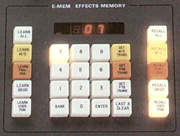
Electronic memory module (E-MEMTM of Grass Valley Model 200) (courtesy GVG-Tektronix)
|
Some more sophisticated switchers have an ability to store and recall all or part of the setup that you�ve so meticulously put together. You can save information on which sources have been selected on which buses, how your keyers have been set up, the colours of your background generators and wipe borders, wipe types, auto transition times, and other related things. There are often several memory banks into which you can store information, for different shows or portions of programs. This is especially useful in such quick turnaround situations such as complicated live to air news broadcasts, or often used effects in post production environments. |
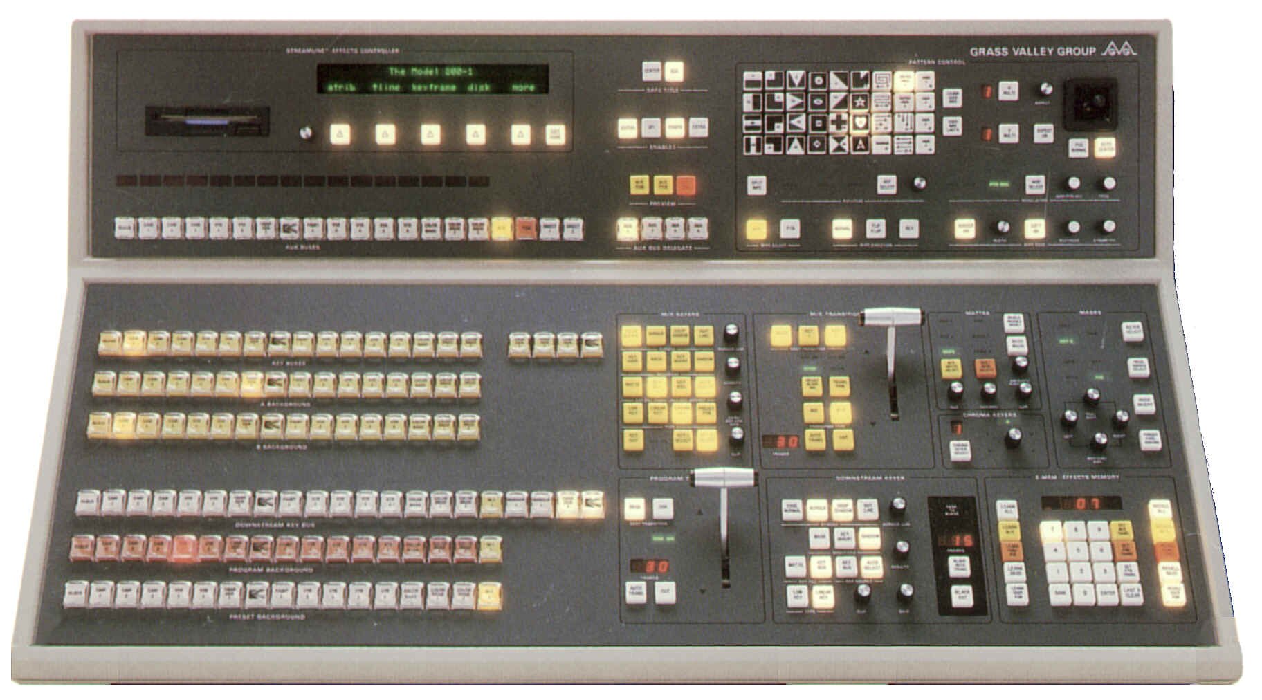
Grass Valley Model 200-1 Switcher (courtesy GVG-Tektronix)
Click on the picture for a bigger view |
Video and processing flow diagram of typical single M/E switcher
Click on the picture for a bigger view |
Digital Video Effects
Digital video effects are made possible by devices that change the normal analog video signal into digital information. This information lends itself readily to all sorts of manipulation. Although quite complicated technically, the principle of digital video effects is relatively simple. The DVE equipment can grab a video frame from any video source, change it into digital information, manipulate it in a variety of ways, and display it. The manipulation information can be stored and retrieved on demand.
Digital conversion of analog video can be compared to changing a photograph into a mosaic of the same scene. The photograph shows you a continuous change of colour and brightness. The digital mosaic presents a great number of discrete picture elements (pixels), each one having a solid colour and brightness, and its own assigned address within the picture. If you want to change the shape of an object within the mosaic, you can take out some of the pixels, or add some. You can paint onto the picture by changing some of the pixels individually, or in groups, without affecting other areas of the picture. If you remove some of the pixels in a linear organized fashion you can make the picture smaller; adding some in the same way, enlarges it.
All of this manipulation is done very quickly. There are about 400,000 individual picture elements (pixels) in one frame of video, and often several pixels will need to be processed just to generate one output pixel. It�s not unusual for a modern DVE to perform in excess of 20 billion mathematical operations per second!
When digital video effects are interfaced with the standard analog effects of a switcher, the possibilities for visual effects are virtually endless. Let's consider some of the effects possible.
Size and Shape
|
An almost unlimited variety of effects are available to manipulate the size and the shape of the image. They include compression and expansion, aspect ratio change, positioning and point of view change, perspective, flips (horizontal and vertical), and automatic key tracking.
Compression and expansion involve the basic making smaller and larger of an existing video picture - it can be the size of a small point, or larger than its original size. If you were to expand a picture to greater than its "times one" size, you would begin to notice that each pixel became, in fact, a small block - you'd see the mosaic effect on the picture. To reduce this artifact, special mathematical formulas are applied to the picture to average out adjacent pixels, adding more video information at the hard edges between each. This is called antialiasing.
With DVE, you can change the traditional 3 x 4 (three units of height to four units of width) ratio of standard television pictures to make it anything you like, creating some rather unusual effects.
The compressed picture can be positioned anywhere in the frame. It can also be tilted. This looks like the image is placed on a graphic card that has been adjusted so you are looking "down" it at an angle. The severity of this tilt can be adjusted to make the image quite stretched.
|
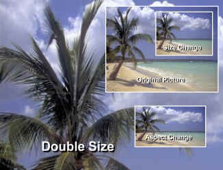
Size and shape manipulation in a DVE
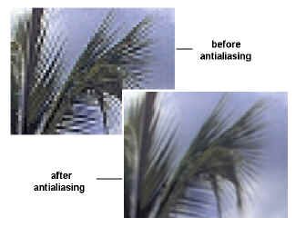
The effect of antialiasing
|
|
Key gate (or alpha channel), DVE manipulated picture, and resulting output of auto key tracking (courtesy Sony)
|
Auto key tracking refers to the automatic change of image size and position of a keying video insert. For example, if you make the key area larger, or move around the foreground image, the compressed picture for the matte insert automatically moves and expands to fill the cutout area. |
Multi-Image
| The multi-image effects include dividing the screen into various sections (split screens), or into many repetitions of the same image (echo). With DVE equipment, you can split the screen into quadrants (quad split) or many more areas, each repeating the image. In more elaborate systems, you can feed several separate images into the various screen "tiles," then select any of them and expand it to full frame. The echo effect is created when you repeat the image as though it were placed between two opposite mirrors. |
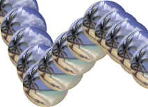
DVE multi-image sample (the picture has also been warped into a spherical shape)
|
Warp
| Once the initial effects of size, shape and positioning had been perfected in the early 1980s, DVE manufacturers sought out even more spectacular effects. This newer generation of picture manipulation is usually known as warping, and involves effects that turn images into spheres, waves, water droplets and page turns. As well, images can now be placed onto geometric objects generated by other computers. This process is known as mapping, and means that surfaces, textures and images can be wrapped around other objects and forms. |
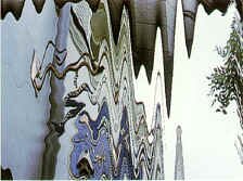
Typical image warping (courtesy Sony)
|
Light and Texture
Because you are dealing with numbers representing certain individual discrete picture elements, you can manipulate the size and shape of an image, and its light and texture. These effects include polarity reversal (where all light areas are turned dark, and vice versa), posterization (reducing the picture to fewer possible colours), solarization (where the picture�s lightest elements are turned dark) and mosaic (where the image's resolution is diminished, resulting in the exaggeration of the digital process, thus creating a picture of discrete rectangles).
Motion
The language of DVE motion is the language of cartoons - "zoom to here," "flip over there," "bounce into this." Some of these terms have been coined by DVE manufacturers, others by imaginative (and tongue-tied) production personnel. In essence, motion effects are any of: continual changes in picture size and position, zooms, rotations, and bounces.
You can pan and tilt a DVE picture, much as you can a camera shot. You can slide a picture off the screen, revealing another. When one picture leaves while another enters, this is a push-off or push-on. Zooms are self-explanatory; notice though, that DVEs can go from very tiny pictures to overblown ones quickly and smoothly. Also, the entire picture moves when you zoom with a DVE; cameras lose the peripheral areas of the picture (or gain them) when zooming in and out.
You can rotate an image on all three axes: the x-axis, representing width; the y-axis, representing height; and the z-axis, representing tilt. In the real world, we think of x-axis rotation as flip (like a flipping coin); y-axis rotation can be considered revolving (like a revolving door); z-axis rotation should be spin (like a steering wheel). Not in the DVE world, though - everybody has their own phrase for these types of motion. This results in much hand-waving and flailing about at the production console, making live television production look very exciting and glamorous.
Multi-Channel Capabilities
Many DVEs will allow you to perform effects on more than one incoming video source at a time. This is called a multi-channel DVE. With the use of special dedicated integrated circuits, the previously prohibitive cost of such manipulation is now within reach of many mid-range production facilities.
Stillstores
|
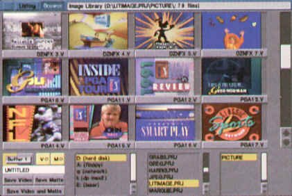
Stillstore selection screen (courtesy Dynatech)
|
A stillstore is a device used to store electronically many freeze frames for later recall. They usually allow a single field of video or a full frame to be frozen. This is accomplished by locking the video in question into a conventional framestore device. The digital data contained there is then transferred to a computer hard drive, and can hold many images, sometimes thousands. Stillstores also usually have the ability to save all the images from the hard drive to a tape drive or CD-ROM, allowing a "back up" of all the images to be saved, in case of hard drive failure.
Selection of a particular image for recall is accomplished by entering a particular frame number, or selecting the image from a listing of available ones. The listing can be in text form, or by way of a series of several small pictures (thumbnails) displayed simultaneously on a video monitor. Once the desired picture is selected, it is quickly recalled from the hard drive and read into the framestore for display and production use.
|
Generated Graphics
The advantage of electronically generated graphics is that they can be directly integrated into the television system. They eliminate the often time-consuming intermediate steps of preparing a camera graphic and shooting it.
Character Generator
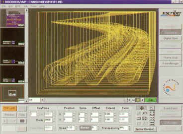
Character generator composing screen (courtesy Inscriber)
|
The character generator looks and works like a typewriter, except that it writes letters and numbers on the video screen instead of paper. This titling device has all but replaced the conventional studio card titles, and has become an important production tool. The more sophisticated character generators can produce letters of various sizes and fonts, and simple graphic displays such as curves and rectangles (blocks). In addition, backgrounds can be colourized.
To prepare the titles or graphs, you enter the needed information on a computer-like keyboard. You can then either integrate the information directly into the program in progress, or store it for later use. Whether it is stored on computer disk or in the generator's RAM (random access memory), the screen full of information is keyed to a specific address (electronic page number) for easy and fast recall.
Most character generators have two output channels - a preview and a program. The preview channel is for composing titles. The program channel is for actually integrating the titles with the major program material. The preview channel has a cursor that shows you where on the screen the word or sentence will appear. By moving the cursor into various positions, you can centre the information, or move it anywhere on the screen. Various controls allow you to make certain words flash, to roll the whole copy up and down the screen, or to make it crawl sideways. More sophisticated generators can move words and graphics on and off the screen at any angle, and at any of several speeds.
|
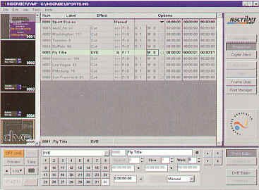
Inscriber sequencing screen (courtesy Inscriber) |
Graphics Generator
|
With graphics generators, you can draw images on the screen. These units are also called video art, or paintbox, systems. You draw onto an electronic tablet with a stylus. An output monitor immediately reflects your artistic efforts, and another one offers a series of design options (such as colour, thickness of line, styles of letters, or special effects) to improve your art work.
Newer systems will allow you to change the size and position of a graphic so that it can be used full-frame, in an over the shoulder position (for news), or in lower third for information display. More than one original image can be integrated into a new full-frame composite (a montage). Character generators are now often part of the software package. Retouching (softening edges, adding or removing highlights, matching colours, blending objects into their backgrounds) is commonly available.
Most graphics generators work in real time; your drawing is immediately displayed on the screen. Less sophisticated paint boxes take a moment before they display the effects. Also, better quality units have built-in circuits and software to prevent aliasing (jagged details on diagonal lines). These are hidden by slightly blurring the edges of the lines.
Personal computers are now often used to generate television graphics, both as character generators and paintboxes. Some amazing effects can be produced with these easy to use graphics machines. These systems have an internal board to convert the regular PC output to standard NTSC scanning.
|
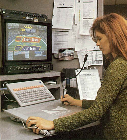
Typical graphics workstation (courtesy Quantel)
|
One word of caution concerning electronically generated graphics and RAM. This is a temporary memory, which forgets everything as soon as you turn off the power. If there is a power outage, your art is lost and you have start all over, unless you have transferred the RAM information to disk. If you pre-program a large quantity of electronic graphic information, do not wait until you are finished all of it to transfer it to disk. Periodic transfer is the safest way of ensuring your work does not evaporate into the electronic ether.
Virtual Sets
From the beginning of television, the bulk of video picture creation has been done with television cameras. In the 1970s, video character generation equipment was invented that relieved us from the tedious task of hand lettering title cards with peoples' names and place identification. Shortly thereafter, with the availability of larger computer hard drives, electronic still store equipment was developed so that we no longer had to rely on the projection of 35 mm slides within a film telecine, or picture cards shot with a camera, to access non-moving video material. Modern computer technology now allows us to record and play back moving video from hard drives, and animate, morph and manipulate video in any way, limited only by our fertile imagination.
We have, over time, tried with varying degrees of success to superimpose live human beings over other video materials. The first attempts (in the days of black and white television) were made by shooting talent (who would not be wearing dark colours) in front of a black limbo background. The black was keyed out, and could be replaced with a second video source.
This technique was refined in the 1960s with the popularization of colour television, and with it, the ability to choose a particular colour for the keying effect. This allowed talent to wear anything that wasn't the particular hue of the now familiar "chromakey" background (usually bright green.) This method really hasn't changed in over a quarter of a century for television, and has been used since the 1950s in the motion picture industry, where it is called "blue screen" or �green screen.� The chromakey technique requires that the camera and the background information be "locked off," that is, there can be no camera movement from either of the two video sources or else the illusion of the person appearing in another environment is lost.
Today, thanks to the impressive processing power of parallel connected computers, we have the ability to move the camera in any direction we wish. This is achieved by creating an entirely fictional world within the computer - a virtual set. While experimentation in this field has been going on for some time, a fully-featured complete system was first shown at NAB in 1994.
Set Design
First, a virtual set must be designed by the manipulation of three dimensional objects in a computer database. Designers of virtual sets must have studio planning expertise along with 3D modelling and image generation knowledge. They create the new set in a "wire frame" mode (one in which the edges of the objects in the set are modelled), and then cover the frame with various colours and textures (an operation called texture mapping) until the desired look is achieved. Lighting of the virtual set is also done in the computer, and must be matched later on by identical (or at least complementary) lighting in the blue screen studio.
Camera Movement
Camera movement must be tracked in all dimensions, so that the computer will know where and how far to move the virtual set relative to the framing and positioning of the live video. This can be done in a number of ways (or in combination.)
Head and Servo Tracking
The most obvious way of tracking camera movement is to put rotary encoders on every moveable element of a camera mounting: tilt, pan, pedestal (vertical motion), trucking, and dollying. In addition, the camera's zoom, focus and iris servos must be monitored for changes in framing size, sharpness, and light level. All of these elements of the live shot must be constantly examined, updated, and sent as data to the graphics computer. In earlier virtual set systems, this was done with high reliability and excellent precision.
External Pattern Recognition Systems
The main disadvantage with the head and servo tracking system is that handheld cameras do not, by definition, fit the tracking paradigm - they have no camera head as a reference point. Other systems have made use of patterns on the chromakey walls or in the grid for relative positioning information.
|
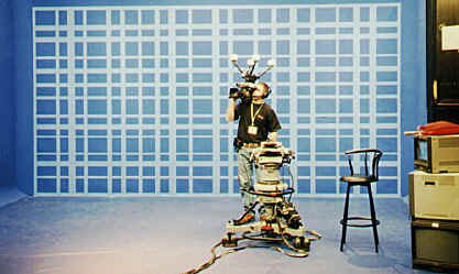
Orad grid system
|
One of the more popular systems for positioning information has been developed by Orad. This involves a distinct plaid-like grid system on the studio wall which, because of its nonlinear details, can be recognized by the host computer and can be analyzed for tilt, pan, pedestal, trucking and dollying information. Another system involves a series of circular patterns mounted on the ceiling grid, and viewed by a small black and white CCD camera mounted vertically on the camera which is doing the actual live video shooting. In addition, either of these pattern systems can be augmented by infrared LEDs mounted on either the shooting camera and/or the on air talent. These beacons, in turn, are viewed and identified by black and white cameras located around the periphery of the studio. All of these systems (in varying combinations or by themselves) allow recognition of a unique position within the studio. |
The insertion principle is the same as chromakey - the removal of a particular hue of blue and its replacement with the computer generated 3D world. Usually, a more sophisticated chroma removal technique - Ultimatte - is used, which allows fine tuning not only of the blue aspects of the key, but also sensing and manipulation of luminance to create a more realistic superimposition.
It's possible to have multiple cameras in a virtual set environment, although the interswitching of foregrounds and backgrounds understandably becomes more complex.
Synchronization
Because of the time it takes to constantly update and render the positioning and movement in a 3D virtual set, there is a several frame delay between the movement of the camera, and the final resting position of the updated set. This must be compensated for by introducing a digital delay unit between the camera output and the keyer which will do the final superimposition. On air talent, of course, will find that they will go through a certain motion (blinking, a sweep of their hand) and, a fraction of a second later, the same action will occur on the studio monitors. Talent microphones and other associated audio must also go through the same digital delay process to maintain synchronization.
Applications
| Virtual sets, applied creatively, can be used in a range of applications. One local television station in southern Ontario, OnTV, began using a virtual set for their newscast in May of 1999. Virtual sets also allow the viewer to be taken into universes otherwise unattainable, for example, inside the workings of an internal combustion engine, making this technology very useful for industrial or corporate training video. Children love imaginative worlds and places, so this is a logical extension of creative children's programming. Other real time effects, subtly used, can be just as effective: monitors that drop down from the grid, revealing additional video information; walls or ceilings that remove themselves to reveal nature or the cosmos; and surfaces that morph into various conventional or unconventional skins: bricks, wood, or waterfalls. |
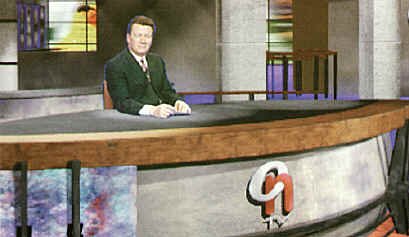
OnTV's virtual news set (courtesy OnTV)
|
Things To Think About:
Switchers are the video equivalent of the audio console and associated effects equipment.
Their complexity has evolved from wanting to cut between video sources, to dissolving, to wiping, to layering one source over another (keying). There are basic principles common to all of these effects.
Know your switcher - make it your friend. The better you are able to understand how it works, the more you will get out of your video program, regardless of what position you hold in the production.
It�s all just routing sources from one place to another, modifying things as we go.
DVEs have been around for about 25 years and have evolved, due to advances in technology and the wants and desires of production personnel.
Know some basic DVE effects and how to express succinctly what you want without slurring your words.
Graphics generating devices (stillstores, character generators, paintboxes) have grown into multi-purpose, often PC-based, integrated systems. Know the basic capabilities of them all, and how they link together, and integrate into the production environment. Again, the more you know about them, the more useful they�ll be to your production.