


 |


"Time has convinced me of one thing. Television is for appearing on, not looking at."
-- Noel Coward (attributed)
Black and White Cameras
The Camera Imaging Device
The principal elements of a typical black-and-white television camera are the lens and the camera imaging device. This used to be a camera tube (with its associated scanning and focusing coils), but now is a CCD. The lens focuses the scene on the front end of the imaging device.
|
CCDs
Broadcasters have used charge-coupled devices (CCDs) for ENG cameras since the early 1980s. Their light weight, low cost and high reliability allowed CCDs to gain rapid acceptance. Manufacturers now produce these devices for use in professional and consumer video camcorders.
|
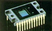
A CCD chip (courtesy BTS)
|
|
The first step in creating a camera image is to gather light. CCDs are rigidly and permanently mounted, usually to the prism itself. There is no possibility for adjusting the scanning process. Lens manufacturers, in turn, standardize their product to work under stringent conditions.
How CCDs Work
There are three sections in your average CCD. An array of photo diodes is positioned at the output of the prism. As varying amounts of light strike the diodes, those that are illuminated become "forward biased", and a current flows that is proportional to the intensity of the light.
The shift gate acts as a switch. This permits the current from each diode to be stored in a solid state capacitor in the CCD. As we know, capacitors store voltages, and these little guys are no exception.
|
|
The CCD analog shift register deals with the charges coming from the capacitors. Each of these registers has an address decoder that allows each portion of the image to be individually addressed. An address encoder cycles through the field of photosensitive registers, and reads out the analog voltages for each pixel. The speed of operation of this decoder is synchronized to the scan rate of television.
The CCD analog shift register actually performs two functions. First, all of the shift gates can provide their light intensity signals at once. This is sort of like a camera shutter opening for a brief instant to let light pass through, and closing and staying closed while the film is advanced. And the variable "shutter" control on a CCD camera lets you perform high speed video sampling - great for sporting events featuring blur-free slow motion playbacks. Second, the serial reading of all of the CCD chip's individual storage elements provides image scanning, somewhat automatically - no electron beam required.
|
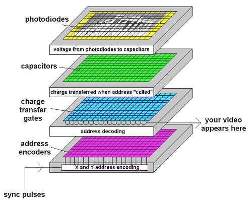
Basic CCD principles
|
The actual transfer of the voltages out to the real world is the key to why CCDs are so ingenious. The CCD unit can transfer the voltage from cell to cell without any loss. This is called charge coupling, which is how the CCD gets its name: Charge Coupled Device.
When the transfer gate of a CCD image sensor is activated, the CCD's clocking circuitry moves the contents of each picture cell to the adjacent cell. Clocking the shift registers in this manner transfers the light input value of each cell to the output, one value at a time. The CCD chips provide their own scanning circuitry, in a way. The last cell in the chain sends its voltage, in turn, to the output circuit of the chip. As an added bonus, cycling through all of the cells this way will not only send out all of the stored voltages, but also discharges all of the cells, too. Everything goes back to normal and the cells are ready to take in a new analog voltage value.
Colour Cameras
Three Chip Cameras
|
Colour camera head end
|
The three electrical signals that control the respective beams in the picture tube are produced in the colour television camera by three CCD (Charge Coupled Device) integrated circuit chips. The camera has a single lens, behind which a prism or a set of dichroic mirrors produces three images of the scene. These are focused on the three CCDs. In front of each CCD is a colour filter; the filters pass respectively only the red, green, or blue components of the light in the scene to the chips. The three signals produced by the camera are transmitted (via colour encoding) to the respective electron guns in the picture tube, where they re-create the scene. |
One Chip Cameras
A one-chip CCD camera uses red, green, and blue filters over alternating pixels. Instead of using a prism, we implant microlenses that contain colour filters over each row of CCD cells. Each tile of this mosaic is about one square micron in size (a thousandth of a millimetre). Keep in mind that this will let in only about a third of the available light, since the filters block so much illumination.
Home Camcorders (One Chip)
|
In home camcorders, we cheat a little...well, actually a lot. We use cyan, yellow, magenta, and green filters instead of RGB filters.
The first two pairs of colour lenses (magenta + yellow, and green + cyan) filter out luminance and the R-Y colour difference signal. The second two pairs (green + yellow, and magenta + cyan) filter out luminance and the B-Y colour signal. The system works, believe it or not, because the analog signals stored under each of the eight lens elements represent various mixtures of coloured light, which can be reconstructed to create a single correct pixel of colour video.
The colour mosaic method is limited by the ability of CCD manufacturers to make these specialized microlenses and position them accurately over the CCD pickup device. As a result, the output of these one chip systems, while of remarkably high quality, can't really compete with true NTSC video quality. The second system described here will make the camera twice as sensitive as the RGB one chip CCD method, but the colour reproduction at low light levels isn't as good, because the RGB information is derived arithmetically (the subtraction of two small numbers with lots of noise gives poor accuracy and high noise.)
|

Home camcorder one chip CCD system (courtesy Broadcast Engineering)
|
Lenses
|

Basic lenses
|
An optical lens is a device that forms an image by refraction. A simple lens consists of a single piece of glass, or other transparent material, having two opposing faces, at least one of which is curved. The "burning glass" for concentrating the sun's rays has been known since ancient times. The magnifying property of a simple lens was recorded by Roger Bacon in the 13th century.
A lens is said to be converging, or positive, if light rays passing through it are deflected inward, and diverging, or negative, if the rays are spread out. Converging lenses are thicker at the middle than at the outer portion, while diverging lenses are thicker toward the edges. The surface of a lens can be concave (curved inward), plane (flat), or convex (curved outward).
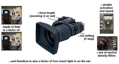
The focal length of a single lens is the distance from the lens to the point at which incoming parallel rays focus. That is, when an object is at an infinite distance away, and you can focus the real image on a screen, the distance from the centre of the lens to the screen is its focal length (see Fig. A.) Infinity, for sake of argument when dealing with practical camera lenses, is a couple of hundred feet away. Long lenses (or, zoom lenses at maximum zoom) have less depth of field than short lenses (or, zoom lenses used for wide shots).
In a negative lens (see Fig. B), rays do not actually come to a real focus, but appear to start from a point called the virtual focus. The focal length of a diverging lens is considered "negative."
In the case of Fig. C, we have created a very simple zoom lens that can vary its focal length by changing the distance between the two lens elements.
|
| The zoom lens was invented in 1956 by Pierre Ang�nieux. Before that time, in order to change focal lengths, the camera operator had to "rack" from one lens to another, available from a selection on a lens turret. |

Turret lens on RTA camera from the �70s
|
|
Real and virtual images
|
A simple convex lens, or magnifying glass, will produce a virtual image if the object is either at the focal point or between the focal point and the lens. If you look through a magnifying glass in this case, light from the object passes through the lens, and the eye focuses it onto the retina. The result is that you can see an image, and the object appears enlarged to you, behind the lens. That's the virtual image.
If the object is beyond the focal point of the same lens, a real image can be formed. A magnifying glass held in front of a light bulb will cause an image of the filament to be projected onto a screen or wall across the room. This is how it is used in a camera.
|
F/ Stops

Relative sizes of lens apertures
The f-number of a lens is the ratio of the focal length to the lens diameter. Lenses of large diameter have small f-numbers and hence greater light-gathering power than lenses of small diameter or large f-number. As an example, when we come across a 2" wide lens with a maximum iris opening of 1", it is considered an "f/2" lens.
|

Iris from inside a lens
|
We come across f-numbers when we speak of the iris of the lens, and they are usually expressed as a series of numbers on the iris ring. For example, If a 2" lens is opened to a �" iris hole, it is set at f/4.
F-numbers (or f-stops) look strange: f/1.4, f/2, f/2.8, f/4, f/5.6, f/8, f/11, f/16 and so on. You'll notice that these numbers don't double each time. What they represent are the diameter changes of the iris setting, relative to one another. For each change by a factor of 1.41 (the square root of 2) in the diameter of the iris opening, the area of the opening doubles. This explains the unusual numbers. Remember that the amount of light passed by the lens is doubled each time a lens iris is adjusted to the next lower number.
|

"Stopping down" increases your depth of field - more subjects, over a broader range of distances, will be in focus
When "stopping down," your depth of field increases - the distance between the minimum and maximum distances within which you can get something in focus, increases. You've noticed that a tiny point of light, when pulled out of focus, becomes a circle. If you pull focus just a very small amount, though, the point is still a point. It hasn't widened up yet, though you have, in fact, changed the focus of the lens. This is because your focus movement is not great enough to change the perceived image focus, as registered on the face of the camera imaging device. The imaging device only has a certain amount of resolution, and this small movement hasn't affected the focus to that great a degree.
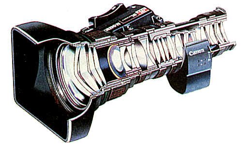
Modern video camera lens (courtesy Canon)
If you close the iris, you narrow the area through which light rays pass through the lens and therefore allow only the more parallel rays. These are the ones passing through the centre of the lens (which bends light the least). Objects at greater distances from each other are able to remain within this range of camera resolution. You don't get something for nothing, though - you lose some of your light to increase your depth of field.
|
Larger Iris
|
Smaller Iris
|
|
smaller f/ stop "number"
|
larger f/ stop "number"
|
|
lets in more light
|
lets in less light
|
|
depth of field decreases - fewer things in focus from foreground to background
|
depth of field increases - more things in focus from foreground to background
|
|
Note: a Neutral Density filter allows you to open up to a larger iris (smaller f/ stop)
|
Operational Principles & Features of Broadcast Video Cameras
Audio Level and Input Controls
Many cameras have audio input level pots - adjust as required. Also, they will usually have a switch to select which type of level (mic or line) is being sent to the camcorder back. Some cameras have an on-board microphone (often marginally acceptable, since it picks up the camera motor noise) and this can be selected as well.
Time Code Selection
|
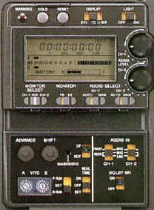
Camera side (courtesy Sony)
|
Many cameras will allow you to preset the time code with pushbuttons, along with entering additional information in "user bits" of the code, and selecting whether the code generator will run only when you press record (REC RUN), or run all the time, like a normal "time of day" clock (FREE RUN). Some cameras have a time code input (TC IN) connector to allow connection of an external time code generator, the code of which will be recorded on your camera tapes. |
Filter Wheel
| Cameras have various neutral density (ND) and colour correction filters mounted on a filter wheel. Most of these wheels also have a "cap" position as well. The colour correction filters are used to reduce the blue colour temperature of sunlight, since ENG cameras are nominally balanced for tungsten (3200 degree Kelvin) lighting. Some correction filters also have an ND factor added. |
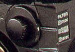
Filter wheel (courtesy Sony)
|
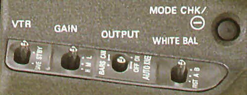
Camera front side controls (courtesy Panasonic)
VTR Save/Standby Switch
This switch (on some cameras) allows you to warm up some of the VTR circuits without actually activating the record head head. To record, flip the switch to "VTR Standby."
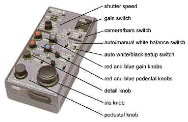
Gain Switch
This two or three-position switch allows you to gain more signal strength when working under very low light conditions. Although the gain allows you to work in a low light environment with little effect on the colours of the scene, it cause the pictures to become progressively noisy and soft because of the video amplifier noise and wide open lens aperture.
Output Switch
Allows you to switch either from the picture output or colour bars. You should always place bars at the head of each tape when shooting in remote situations, so that the levels you record can be properly reproduced in the edit suite or whenever the tape is played back.
White Balance Selector
This switch has such positions as MEMO (automatically adjusts the white balance, and stores it in internal memory); PRESET (a factory setting, sometimes can be overridden by the camera operator; and AUTO TRACK (the camera attempts, with varying degrees of success, to keep a check on the colour balance of the scene and correct for it "on the fly".)
Remote Control CCU (Camera Control Unit
Shutter
|
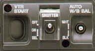
Camera front, under lens (courtesy Sony)
|
With CCDs, we can now have action-freezing shutters built into our cameras (see how CCDs work, earlier in this chapter.) With shutters, keep in mind that a higher shutter speed means less light available, so the wider the iris will have to be (or the more light you�ll have to pour on the scene.) Shutter speeds can vary from "off" (no shutter activation) to 1/8000 of a second. |
Auto White/Black Balance
Flip this switch down to initialize an automatic black balance process. This will ensure that the black information in your shot has no undesirable colours.
While shooting a white subject (for example a piece of white paper), set the switch up and your camera will remove the colour subcarrier from your shot, thus ensuring that your camera is colour balanced for the type of light under which you're shooting.
Audio Connectors
| All cameras will have XLR broadcast audio input connectors, one for each of the two available channels. Some may have an AUDIO OUT for monitoring playback within the camera. Every camera will have a headset jack which accommodates a 1/8" standard headset plug (a regular portable cassette or CD player headset works just fine.) |
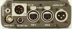
Camera rear (courtesy Panasonic)
|
Video Connectors
|
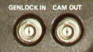
Genlock and auxiliary camera output BNC connections (courtesy Panasonic)
|
Almost all cameras have a VIDEO OUT connector, to allow you to see what�s in the camera�s viewfinder for monitoring and checking purposes. In addition, there may be a second video output, and a connection for locking the camera�s scanning to an external sync generator (GENLOCK IN). |
White Clip
All cameras have white clip circuits to prevent the output signals from exceeding a practical video level, even if highlights appear in the picture. Video won�t go over a preset limit (usually 110 to 120 units) even if the scene has such highlights in it.
Zebra Stripe Level Indicator
This generates a "zebra stripe" pattern in the viewfinder by which you can judge whether you're set for 70, 80 or 100 units (or more) of video level. Any picture elements above peak level will have the stripes superimposed on them.
Scene File
Scene files are small amounts of adjustment data that can be saved in semiconductor memory within the camera itself. Parameters that can be saved include white balance, iris and black levels, gamma, detail level, camera gain, iris settings and other information. The memorized values can be recalled by pressing the corresponding scene file button on the CCU. This allows the camera operator instant adjustment when moving from one shooting condition to another.
Detail Level
Image enhancement is used in all cameras to improve picture quality. Image enhancement is accomplished by raising the contrast between the light-to-dark and dark-to-light areas of a picture. This is done by "overshooting" the signal at these transition points. The detail correction control allows you to vary by how much this overshooting will occur.
Try This At Home!
Take a piece of cardboard and cut a long slot in it (how big doesn�t really matter, but big enough that you can see through it.) Turn on that old box fan sitting in your window (low speed will do). Wave the cardboard back and forth really fast while looking through the slot at the fan. Play with different "wave" rates. This is the principle behind a television camera�s shutter. You�ll see the fan blades� rotating action has actually "stopped".
Your roommates, however, will see that all those hours of studying Television Technical Theory are finally getting to you...
Mountings
Cameras can rest on many different objects: tripods, pedestals, your body (with or without a mount), sandbags, and cranes.
Tripods
A group of three legs connected with various fastenings to raise or lower the overall height of the camera head. Sometimes a dolly is fastened to the bottom, a triple-armed unit with a wheel on each arm, to allow fluid motion around a studio or other smooth surfaced environment. At other times a simple "spreader" or "spider" is used at the base of the three tripod legs to keep them stable and to prevent them from sliding out from underneath the camera.
Pedestals
|
Vinten pneumatic pedestal as in Studio A (courtesy Vinten)
|
With the studio pedestal you can dolly very smoothly, and elevate and lower the camera easily while on the air, by releasing the pedestal column locking ring or handle.
Steering is accomplished in one of two ways. In the parallel or "steer three" position, all three sets of wheels point in the same direction, and are turned in unison by a steering wheel connected via pins and rods to a chain connected to all the casters. In the tricycle or "steer one" position, only one wheel set is connected to the steering wheel. This allows you to twist or rotate the pedestal to a new orientation on the studio floor, permitting you to get closer to the edges of objects such as risers and graphic stands.
|
|
The two most common types of pedestal are the counterweighted and pneumatic. The counterweighted type consists of a series of lead blocks arranged so as to balance the weight of the camera (and its possibly associated teleprompter). An example of this is the Houston-Fearless pedestals in Studio B.
The pneumatic pedestal substitutes a column of compressed air, contained within telescoping columns, in place of the counterweights. The advantage of pneumatic pedestals are lighter weight and ability to lower the camera further than the counterweighted unit. The disadvantages are cost, and that they occasionally need replenishing of the lost gas that eventually seeps away over time. There are two Vinten pedestals of this type in Studio A.
|
Vinten Osprey pedestal (courtesy Vinten)
|
Your Body
Most portable cameras for ENG/EFP use are designed to be carried on your body directly. The U-shaped section under the camera is theoretically shaped like your shoulder. Special body mounts or braces are sometimes used to distribute the weight more evenly over the shoulder and waist. The disadvantage of body braces is that, unless the cameraperson is well practised, breathing motion is transferred to the camera. This can result in a most unpleasant seasickness effect.
It's important to note that small MiniDV cameras (now available because of their remarkable video quality) should never be used in a handheld way for professional broadcast quality results. The reason is that their light weight makes them too shaky for proper stability and framing. This is one of many things that distinguishes professional looking video from "home camcorder" or amateurish visuals.
Sandbags
For very low (on the ground) shots, sandbags allow a certain amount of camera motion, but enough stability that the camera can actually be left unattended, providing no movement is required. Sandbags also can be used for temporary attended stability when shots are required from less-than-solid positions, such as the tops of desks.
Cranes/Jibs
|
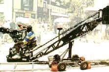
Crane (courtesy Egripment)
|
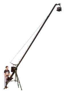
A crane needs at least two operators - one to do the camera shot, and another to move around the dolly and boom. With a crane you can get to within one foot of the studio floor, and sometimes dozens of feet above it. The camera can be swung left and right while panning and tilting, providing opportunity for some excellent effects and creative camera work.
The jib, on the other hand, can be run by one operator, and can do practically the same variety of moves as a full up crane. Its controls also allow you to tilt, pan, focus and zoom the camera. This takes a bit of practice, but jibs can be collapsed, moved almost anywhere, and take little time to set up again. They're very versatile, relatively inexpensive, and fun.
|
Jib (courtesy Stanton)
|
Steadicam
|

Steadicam
|
The SteadicamTM is a camera mount worn by the camera operator. Invented by Garrett Brown in the mid-1970s, it consists of a "vest" to which is attached an articulated arm system. Various springs absorb the wobbles and jitters while you run with the camera. In fact, when you run upstairs or on a mountain pass, your camera shots will come out as smooth as if you had used a camera crane. The Steadicam vest is quite heavy, and only experienced operators can wear it and the camera/monitor combination for an extended period of time. |
Flying Cameras
| For overhead shots ranging over long distances, nothing can compare to a camera mounted in a helicopter. Whether it's a full size chopper with a special camera and swivel mount in its belly (for example, WescamTM), or the completely radio-controlled and microwave relayed video system shown in the illustration (Flying CamTM) it will be an expensive proposition. But sometimes, nothing else will do the job. |
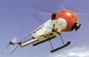
Flying-Cam (courtesy Flying-Cam)
|
Camera Heads
|
Vinten "cam" head as in the studios (courtesy Vinten)
|
A good camera mounting head should be able to counterbalance the camera easily and quickly (with its attendant accessories) by make the panning and tilting easy and smooth for the operator. All heads have separate controls to control the degree of friction ("drag"), and panning and tilting locks.
Cam Head
Usually confined to studio environments, it can counterbalance even the heaviest of studio cameras to permit smooth motion.
|
Fluid Head
For lighter ENG type cameras, fluid heads are preferred, since the cam type of head doesn't allow for minor adjustments with lighter cameras. Fluid heads achieve the counterbalancing effect by having their moving parts operate in a thick oil. Their tensions can be adjusted by a selector ring.
|
Miller fluid head
|
Camera Operation and Aesthetics
Like riding a bicycle, operating a camera is something you learn by doing. There is no substitute for practise. Here we will discuss some operating principles, and picture composition.
Checking It Out and Using It
Studio Shoot
Before beginning a shoot in the studio, check your stuff:
 |
Is your intercom working (talking and listening)? |
|
Are your tilt, pan, drag, balance, locks, and counterweights (if using a pedestal) adjusted properly? |
|
Is your camera cable untwisted and unknotted? Can it uncoil easily? |
|
How's your viewfinder picture quality? Adjust it accordingly. |
|
How are your optics? Does your lens zoom smoothly? Does it focus smoothly? Is your back focus correct? To adjust it, zoom all the way in on a far away specular (small, shiny) object. Focus on it. Zoom all the way back. If the object is still not in perfect focus, adjust the back focus ring at the back of the lens. Repeat this as many times as necessary until the lens tracks focus throughout the zoom. |
|
Is the teleprompter connected? Plugged in? Making a picture? |
During the shoot, pay attention and think ahead:
|
Preset your zoom so that when you land, zoomed in, you will be in focus. But, do not zoom in and out needlessly during shots unless you are presetting your zoom lens. |
|
If you anticipate a dolly, ensure that your zoom lens is as wide as possible. This allows you to dolly with minimum vibration being transferred to the shot. The depth of field at this setting should be large enough so you need to adjust focus only when you land close to the object or event. |
|
When dollying and trucking, start slowly to overcome the inertia and try to slow down just before the end of the move. If vertically oriented pedestal moves are to be executed, make sure that you slow down before it hits the stops at the extreme top or bottom. |
|
Be aware of stuff around you - other cameras, microphones, floor monitors, the floor director. A good floor director will help you to clear the way. He or she also will tap you on the shoulder to prevent you from backing into something. |
|
Watch for the tally light to go out before moving the camera, unless, of course, motion is intended. A good camera operator has the next shot lined up before the director calls for it. Your director will appreciate good visuals in an ad lib show, but do not try to outdirect the director from your position. |
|
Listen to what the director tells all the camera operators, not just you - you'll be able to coordinate your shots with those of the other cameras. Avoid unnecessary chatter on the intercom. |
When the shoot is over:
|
Cap and lock the camera. Push it to a safe place within the studio. Coil the cable into a figure-eight loop. |
EFP Shoot
|
Before you go, check your stuff:
|
Are the batteries charged? Do you have spares? Don't forget to keep an eye on the white balance, microphone and mixer batteries. |
|
Is the VTR working fine? Does the camera make colour balanced, registered pictures? Have you done a test record before you leave? This will ensure that your VTR and your camera are working properly. |
|
Do you have enough tape? Does your recording stock have the little record protection punch-outs still intact, or slid in the right position? Are you sure you�re using the correct type of tape for the camcorder (e.g., oxide instead of metal tape for Betacam SP machines, right size of cassette for DVCPro cameras, etc.) |
|
Does your microphone work? Does your microphone cable work? |
|
Does the sungun work? Do you have a spare bulb? Do you have enough AC cords, bulbs, and adaptors, if you're using 110 volt lighting? |
|
Consider the following as the seed of your own personal ENG/EFP shoot kit:
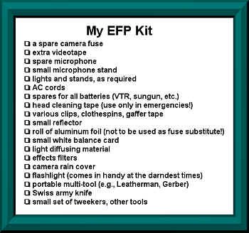
|
During the shoot:
|
Set your equipment up - turn on the VTR and camera. Power up the microphones as required. Do white and black balance. Repeat the balance each time you change locations. If you are in situations with more than one light type, try to place the white balance card so it is lit by both sources. |
|
When shooting, try to keep the camera as steady as possible. Aim the camera with your whole upper body; have your legs absorb all the bumps. To reduce vibration, walk with the zoom lens in the wide-angle position. |
|
If you lose the action, don't worry: keep the camera steady, find out where the subject is, and aim the camera smoothly in the new direction. Alternatively, simply zoom out to reorient yourself to the new situation. |
|
When shooting under low light conditions, you will need to pay more attention to focus than when using a sungun or when in daylight - your depth of field is greatly reduced. Try to avoid fast movements - your camera's inability to shoot reliably in low light will reveal itself as lag. |
|
Shoot with sound at all times. Even if you will be doing full post-production sound later and don't require the on location sound, always record the internal camera microphone at least. This sound will be invaluable in the post-production process for cues, takes, synchronization and other purposes. Never come back from a shoot with a silent tape! This supplies a good background sound source during the edit. When the talent is holding the external mic, don't run away from him or her to "get a better shot." Either you run together, or you must stay put. |
|
Above all, use common sense. Be aware of safety - yours and other people's. In ENG, reliability and consistency are more important than tales of adventure, no matter how spectacular. |
And, after the shoot:
|
Unless the story is going immediately to air, take care of business first - put away your equipment in the established boxes or bags. |
|
Make sure the cassette is removed from the VTR. |
|
Ensure all switches are turned off - don't forget microphone power switches. |
|
Cap the camera. |
|
Roll up all cables. |
|
Put your batteries in the charger. |
|
If the equipment got wet, confirm that everything is dried off thoroughly. |
|
If anything got broken or didn't work right in the first place, don't hide it - get it fixed! |
Filters
For many talented camerapeople, a filter is just the little wheel on the side of the camera. With a little experimentation you can create a universe of film-like effects and images.
The basic video kit should include three groups of filters: 1) correction, e.g., polarizing or graduated filters; 2) colour, e.g., sepia or pastel, and 3) special effects, e.g., star or diffusion. Within these groups are a host of creative tools.
Most camerapeople are familiar with correction filters, since the filter wheel on their camera has a neutral density, to cut bright sunlight, and a colour correction for daylight and tungsten lights. But there is no need to stop there.
| For any high contrast, outdoor work, they should have a polarizing filter. It reduces the glare of snow banks and desert sand. It also cuts reflections from glass and metal, and makes transparent water shots in the Caribbean possible. In general, it is useful to darken a light blue sky and improve the contrast ratio between talent and background. The amount of correction can be adjusted simply by rotating the filter in the mount. |
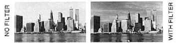
Polarizing filter (courtesy Tiffen)
|
Colour correction filters range from the traditional fluorescent, to a UV reducing Haze, to a new series in red and blue that combine correction and neutral density. Colour correction can be especially useful where the backlight and foreground light are of a different temperature.
|
Graduated filter (courtesy Tiffen)
|
A graduated filter, half colour/half clear, can be used both for correction and colour enhancing. A neutral grey will reduce the intensity of half the frame without adding colour. Darkening high contrast areas such as sky or sand allows for better exposure of the primary subject. A blue filter brings out vivid colours in sky or water, and a pink or tobacco make striking sunsets even in the afternoon. These are also helpful indoors to soften harsh overhead light. |
Full colour filters can give normally "hard" video an emotional range and texture usually associated with film. Pastels evoke images from romantic firelight to nightmarish visions, blues can simulate mornings or evenings, coral filters can warm skin tones, orange can create forest fires. A didymium filter increases saturation of reds and oranges while softening blues and greens. This can make warm visuals on the bluest of days. The most widely used colour filter in video is probably sepia, a time machine that transports the viewer to the fondly remembered past.
| Special effect filters can add a twinkle to an eye or generate special images. Star filters highlight points of light. Use them to accent candles, create sparkles on a client's product, or enhance an eye light reflected in the talent's pupil. |
Star filter (courtesy Tiffen)
|
|

Multi-image filter (courtesy Tiffen)
|
Travel to an altered state with a multi-image, prism, or vari-colour filter that changes colour as it is rotated. Roam from a misty morning to the depths of the bayous with fog filters. Journey to a world of dream or fantasy with diffusion filters. A centre-spot filter will make a client's product stand out in sharp relief by clearly positioning the object in a sea of colour, or surrounded by haze. |
| Because of the increased sensitivity of current video cameras, filters can be used in combinations that multiply both the effectiveness and effects. For example, a pastel and a fog, or a diffusion and a multi-image can be combined. |

Fog filter (courtesy Tiffen)
|
|

Centre-spot filter (courtesy Tiffen)
|
With creative filtering, film makers have been emotionally manipulating audiences for over a century. These same techniques can be used on your next video commercial, story, or show. |
Things To Think About
Cameras mostly use CCDs today - their basic construction is what makes them unique and useful. There are variations on CCDs to give us single chip, two chip and three chip cameras.
Lenses have been around for centuries, and the principles, with which you should be familiar, haven�t changed in all those years.
Know thy camera, and its operational controls.
Cameras can be mounted almost anywhere. Where and how?
Know thy camera lineup, operation and tricks of the trade backwards and forwards - it should be second nature to the videographer.